5-72 B30 Bus Differential System GE Multilin
5.2 PRODUCT SETUP 5 SETTINGS
5
c) ANALOG CHANNELS
PATH: SETTINGS PRODUCT SETUP OSCILLOGRAPHY ANALOG CHANNELS
These settings select the metering actual value recorded in an oscillography trace. The length of each oscillography trace
depends in part on the number of parameters selected here. Parameters set to “Off” are ignored. The parameters available
in a given relay are dependent on:
• The type of relay,
• The type and number of CT/VT hardware modules installed, and
• The type and number of analog input hardware modules installed.
Upon startup, the relay will automatically prepare the parameter list. A list of all possible analog metering actual value
parameters is presented in Appendix A: FlexAnalog parameters. The parameter index number shown in any of the tables is
used to expedite the selection of the parameter on the relay display. It can be quite time-consuming to scan through the list
of parameters via the relay keypad and display - entering this number via the relay keypad will cause the corresponding
parameter to be displayed.
All eight CT/VT module channels are stored in the oscillography file. The CT/VT module channels are named as follows:
<slot_letter><terminal_number>—<I or V><phase A, B, or C, or 4th input>
The fourth current input in a bank is called IG, and the fourth voltage input in a bank is called VX. For example, F2-IB desig-
nates the IB signal on terminal 2 of the CT/VT module in slot F.
If there are no CT/VT modules and analog input modules, no analog traces will appear in the file; only the digital traces will
appear.
5.2.9 USER-PROGRAMMABLE LEDS
a) MAIN MENU
PATH: SETTINGS PRODUCT SETUP USER-PROGRAMMABLE LEDS
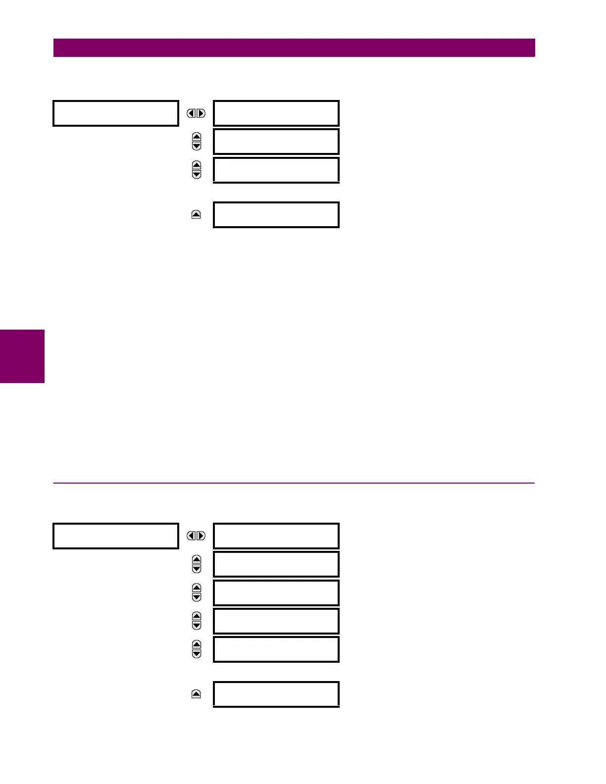
ANALOG CHANNELS
ANALOG CHANNEL 1:
Off
Range: Off, any FlexAnalog parameter
See Appendix A for complete list.
MESSAGE
ANALOG CHANNEL 2:
Off
Range: Off, any FlexAnalog parameter
See Appendix A for complete list.
MESSAGE
ANALOG CHANNEL 3:
Off
Range: Off, any FlexAnalog parameter
See Appendix A for complete list.
↓
MESSAGE
ANALOG CHANNEL 16:
Off
Range: Off, any FlexAnalog parameter
See Appendix A for complete list.
USER-PROGRAMMABLE
LEDS
LED TEST
See below.
MESSAGE
TRIP & ALARM LEDS
See page 5–75.
MESSAGE
USER-PROGRAMMABLE
LED 1
See page 5–75.
MESSAGE
USER-PROGRAMMABLE
LED 2
MESSAGE
USER-PROGRAMMABLE
LED 3
↓
MESSAGE
USER-PROGRAMMABLE
LED 48