5-166 B30 Bus Differential System GE Multilin
5.6 GROUPED ELEMENTS 5 SETTINGS
5
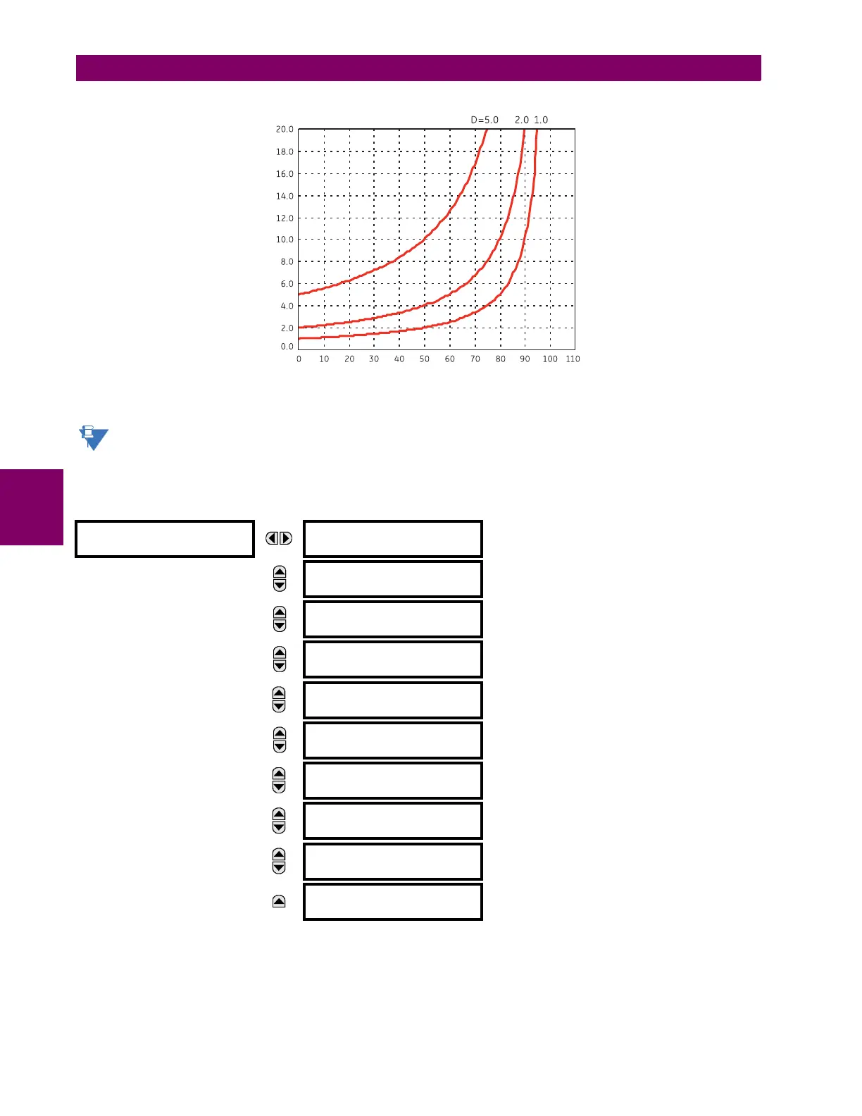
Figure 5–65: INVERSE TIME UNDERVOLTAGE CURVES
At 0% of pickup, the operating time equals the UNDERVOLTAGE DELAY setting.
b) PHASE UNDERVOLTAGE (ANSI 27P, IEC PTUV)
PATH: SETTINGS GROUPED ELEMENTS SETTING GROUP 1(6) VOLTAGE ELEMENTS PHASE UNDERVOLTAGE1(3)
Two undervoltage elements facilitate applications including undervoltage supervision of the main bus differential protection
to prevent maloperation in the event of CT trouble.
PHASE
UNDERVOLTAGE1
PHASE UV1
FUNCTION: Disabled
Range: Disabled, Enabled
MESSAGE
PHASE UV1 SIGNAL
SOURCE: SRC 1
Range: SRC 1, SRC 2, SRC 3, SRC 4, SRC 5, SRC 6
MESSAGE
PHASE UV1 MODE:
Phase to Ground
Range: Phase to Ground, Phase to Phase
MESSAGE
PHASE UV1
PICKUP: 1.000 pu
Range: 0.000 to 3.000 pu in steps of 0.001
MESSAGE
PHASE UV1
CURVE: Definite Time
Range: Definite Time, Inverse Time
MESSAGE
PHASE UV1
DELAY: 1.00 s
Range: 0.00 to 600.00 s in steps of 0.01
MESSAGE
PHASE UV1 MINIMUM
VOLTAGE: 0.100 pu
Range: 0.000 to 3.000 pu in steps of 0.001
MESSAGE
PHASE UV1 BLOCK:
Off
Range: FlexLogic operand
MESSAGE
PHASE UV1
TARGET: Self-reset
Range: Self-reset, Latched, Disabled
MESSAGE
PHASE UV1
EVENTS: Disabled
Range: Disabled, Enabled
842788A1.CDR
% of voltage pickup
Time (seconds)