GE Multilin B30 Bus Differential System 5-191
5 SETTINGS 5.7 CONTROL ELEMENTS
5
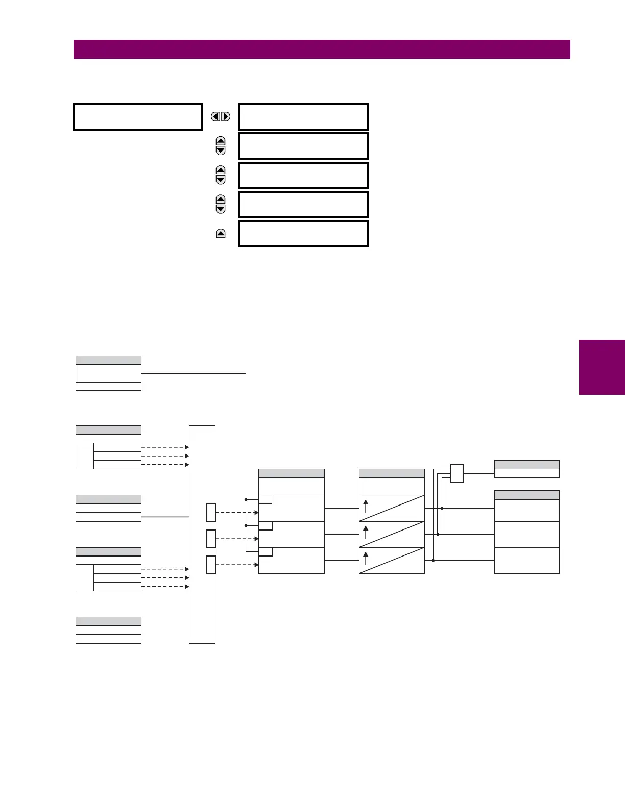
c) CT TROUBLE ZONE (ANSI 50/74)
PATH: SETTINGS CONTROL ELEMENTS MONITORING ELEMENTS CT TROUBLE ZONE 1(2)
This element uses the differential current calculated in accordance with the bus configuration programmed under Bus Zone
1. Operation of this element is therefore completely dependent on the dynamic bus replica, which must be defined first. The
bus differential zones are defined using the path
SETTINGS SYSTEM SETUP BUS. The CT Trouble element 1 detects
CT problems in any of the circuits actually connected to the differential zone defined as Bus Zone 1.
The CT TROUBLE ZONE 1 PICKUP setting specifies the differential current level that defines an abnormal bus state. If the dif-
ferential current in a given phase remains above this level for the time interval defined by the CT TROUBLE ZONE 1 DELAY
setting, CT Trouble is declared for the given phase by setting the appropriate FlexLogic output operand.
Figure 5–80: CT TROUBLE SCHEME LOGIC
CT TROUBLE ZONE 1
CT TROUBLE ZONE 1
FUNCTION: Disabled
Range: Disabled, Enabled
MESSAGE
CT TROUBLE ZONE 1
PICKUP: 0.100 pu
Range: 0.020 to 2.000 pu in steps of 0.001
MESSAGE
CT TROUBLE ZONE 1
DELAY: 10.0 s
Range: 1.0 to 60.0 s in steps of 0.1
MESSAGE
CT TROUBLE ZONE 1
TARGET: Self-reset
Range: Self-reset, Latched, Disabled
MESSAGE
CT TROUBLE ZONE 1
EVENTS: Disabled
Range: Disabled, Enabled
836722A3.CDR
SETTING
SETTING SETTING
FLEXLOGIC OPERAND
FLEXLOGIC OPERANDS
SETTING
SETTING
Enabled =1
Off = 0
Off = 0
CT TROUBLE ZONE 1
FUNCTION:
CT TROUBLE ZONE 1
PICKUP:
CT TROUBLE ZONE 1
DELAY:
CT TROUBLE 1 OP
CT TROUBLE 1 OP A
CT TROUBLE 1 OP B
CT TROUBLE 1 OP C
| Iad1 | > PICKUP
RUN
RUN
RUN
| Ibd1 | > PICKUP
| Icd1 | > PICKUP
BUS ZONE 1A STATUS:
BUS ZONE 1F STATUS:
SETTING
SETTING
BUS ZONE 1A SOURCE:
BUS ZONE 1F SOURCE:
PHASORSPHASORS
DIFFERENTIAL CURRENTS
Icd1
Ibd1
Iad1
Ia
Ia
Ib
Ib
Ic
Ic
OR
. . .
PKP
PKP
PKP
0
0
0