GE Multilin C60 Breaker Protection System 5-189
5 SETTINGS 5.6 GROUPED ELEMENTS
5
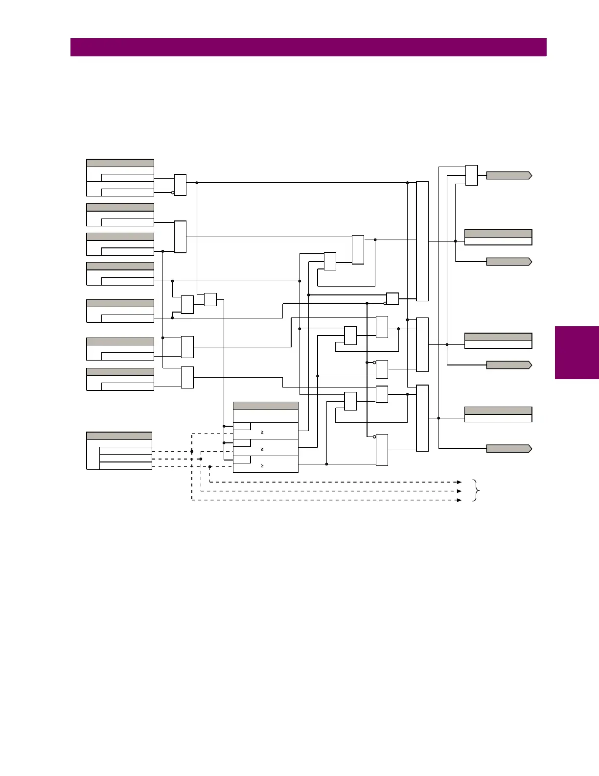
the same overall general concept except that it provides re-tripping of each single pole of the protected breaker. The
approach shown in the following single pole tripping diagram uses the initiating information to determine which pole is
supposed to trip. The logic is segregated on a per-pole basis. The overcurrent detectors have ganged settings. This
setting is valid only for single-pole breaker failure schemes.
Upon operation of the breaker failure element for a single pole trip command, a three-pole trip command should be
given via output operand
BKR FAIL 1 TRIP OP.
Figure 5–75: SINGLE-POLE BREAKER FAILURE, INITIATE
AND
OR
OR
OR
AND
OR
OR
OR
OR
OR
OR
AND
AND
AND
AND
AND
AND
Seal-in path
Seal-in path
Seal-in path
to breaker failure
single-pole logic sheet 3
Function
SETTINGS
Enabled = 1
Block
Off = 0
Phase A Initiate
SETTING
Off = 0
Phase B Initiate
SETTING
Off = 0
Three-Pole Initiate
SETTING
Off = 0
Use Seal-In
SETTING
Yes = 1
Use Amp Supervision
SETTING
Yes = 1
Phase C Initiate
SETTING
Off = 0
SETTING
RUN
IC Pickup
RUN
IA Pickup
RUN
IB Pickup
Initiated phase A
to breaker failure
single-pole logic sheet 2
BKR FAIL 1 RETRIP A
FLEXLOGIC OPERAND
Initiated
to breaker failure
single-pole logic sheet 2
Phase Current
Supervision Pickup
Source
SETTING
IA
IB
IC
SETTING
Initiated phase B
to breaker failure
single-pole logic sheet 2
BKR FAIL 1 RETRIP B
FLEXLOGIC OPERAND
Initiated phase C
to breaker failure
single-pole logic sheet 2
BKR FAIL 1 RETRIP C
FLEXLOGIC OPERAND
OR
834013A3.CDR
IA
IB
IC
OR