[EN] English - K0454 Issue 1 Parts 5
• To prevent a dangerous release of pressure, make sure
that all the related pipes, hoses and equipment have
the correct pressure rating, are safe to use and are
correctly attached.
Cautions
To prevent damage to the display, do not use sharp
objects on the touch-screen.
To prevent damage to the PM 620 module, only use it
within the specified pressure limit on the label.
Before you start an operation or procedure in this publication,
make sure that you have the necessary skills (if necessary, with
qualifications from an approved training establishment). Follow
good engineering practice at all times.
Marks and
symbols on the
instrument
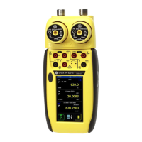
4Parts Refer to the figures on the front cover (A2, B1).
4.1 Key to figure A2 (DPI 620 calibrator)
Complies with European
Union directives
Warning - refer to the
manual
Read the manual USB ports: Type A;
Mini-type B connector
Ground (Earth) ON/OFF
Do not dispose of this product as household waste.
Refer to “Maintenance” (Section 5.5).
More marks and symbols are specified in the user manual
(K0449 - Druck DPI 620
Advanced modular calibrator)
A2 1. On or off button. Refer to “Quick Reference”.
2. CH1 Channel 1 connectors for: voltage (V); frequency (Hz);
resistance (Ω); resistance temperature detectors (RTD):
3W, 4W = 3-wire, 4-wire RTD input; switch operation;
current (mA+, mA-): COM = Common connector
You can also use the GE specified AC probe (Part: IO620-AC)
to measure AC voltages (maximum: 300 Vac).
3. TC Channel 1 connectors for thermocouples.
4. CH2 Isolated channel 2 connectors for: voltage (V); current (mA+,
mA-); 24V loop power supply (24Vo); switch operation
 Loading...