– 53 –
The drive pulley is mounted to the drive motor. It
KDV¿QVRQWKHPRWRUVLGHWRKHOSNHHSWKHPRWRU
cool during operation.
The transmission pulley doubles as a gear for the
mode shifter to lock into during agitation.
Pulley Removal
1. Remove the two 9/16 nuts (one for each
pulley), securing them to the motor and
transmission shafts.
2. 6OLGHWKHSXOOH\VRႇWKHPRWRUDQG
transmission shafts. Torque the new pulley
nut to 110 in. lb. when reinstalling.
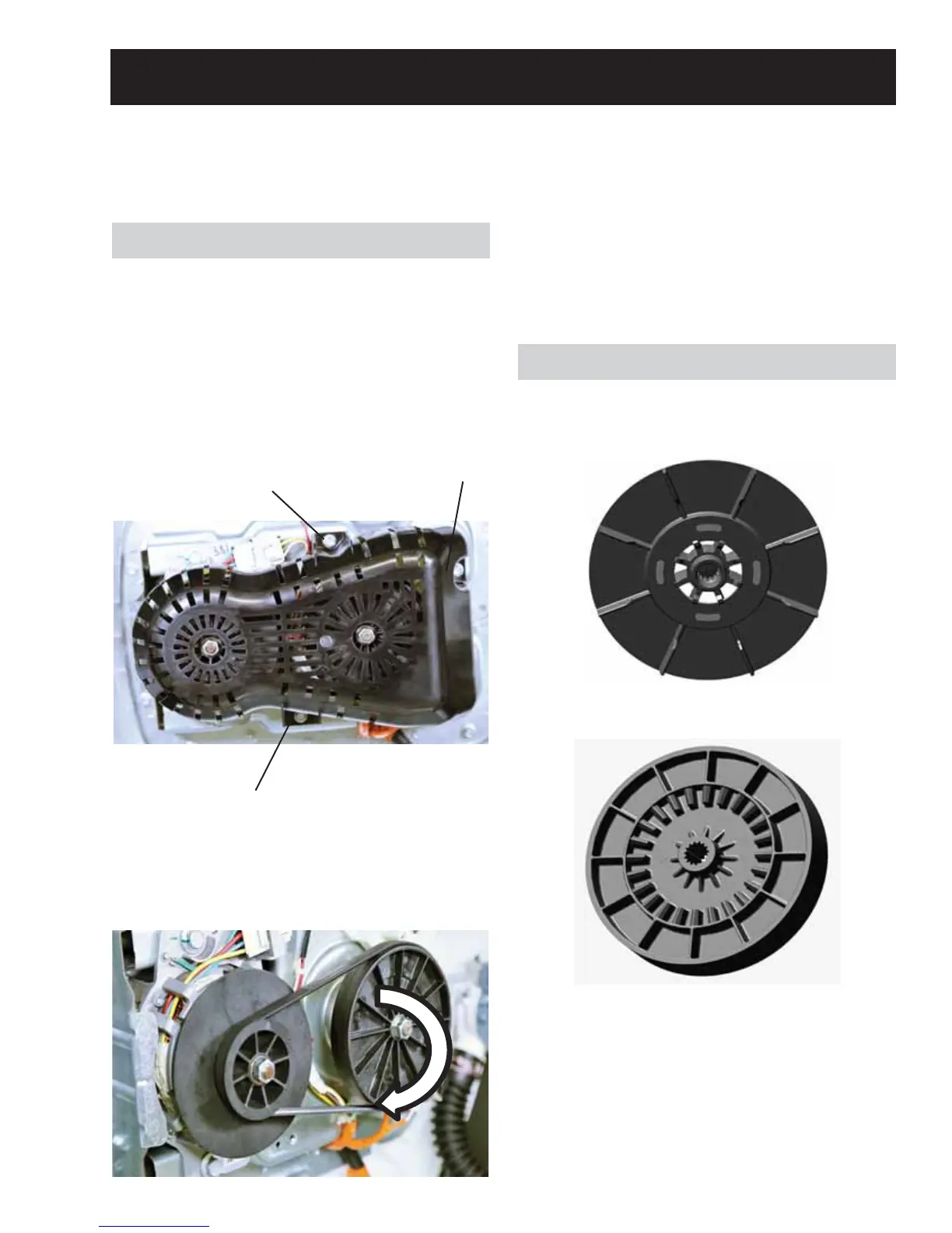
The drive belt has six ribs and can be removed
easily. To access the belt, the belt protector needs
WREHUHPRYH¿UVW
Belt Protector Removal
1. Remove three 3/8 hex head bolts securing the
belt protector to the platform assembly and
set the platform assembly aside.
Belt Removal
1. Rotate the pulley by hand while walking the
EHOWRႇRIWKHSXOOH\
Drive System
Drive Belt
The drive system consists of the belt, pulleys,
drive motor, mode shifter, speed/hall sensor and
transmission. They all operate together to agitate
and/or spin the load in the basket.
Drive/Transmission Pulleys
Belt Installation
1. Put the belt on the motor pulley.
2. Stretch the belt around the transmission
pulley as far as it will go.
3. Rotate the pulley until the belt is centered on
the transmission pulley. Ensure all of the belt
ribs are properly located on the drive motor
pulley.
Hex Head
Bolt
Hex Head
Bolt
Hex Head
Bolt
 Loading...