EasyManua.ls Logo

GE Infinity S User Manual

GE Infinity S
12 pages
To Next Page IconTo Next Page
Page #1 background imageLoading...
Page #1 background image
GE
Critical Power
Infinity S (NE-S) Dual Voltage Power System
Quick Start Guide
[Product Descriptors]
NES4812-23-AC1-PS4-DC1E-LVBD
Read and follow all safety statements and precautions in this guide.
Tools Required:
Cable Crimpers Torque Wrench (0-240 in-lb / 28Nm) 5/16”, 7/16and ½nut drivers
Screw Drivers (#1 Flat & #2 Phillips) Wire cutters and strippers
Step 1 - Mount the System
Mount the system with a minimum gap of 3 inches behind the system to allow proper airflow.
1. Attach the system to the frame using a minimum of twelve (six on each side) 12-24 screws (provided).
Torque to 35 in-lb (4 Nm) - 5/16” socket.
Step 2 – Connect Chassis and DC reference (CO) ground
Chassis Ground lug - #10 or 1/4” on 5/8” centers (not provided).
Minimum 10 AWG recommended.
Torque to 10-32 screws to 30 in-lb (3.4 Nm) 5/16” Socket.
DC reference ground lug - 5/16” or 3/8” on 1” centers (not provided).
Torque to 160 in-lb.
Note: If connecting chassis ground to frame surface remove non-conductive frame coating and apply antioxidant for
connection.
19” /
23”
Width
AC Input
AC1 Molex
AC2 IEC 320 C19
AC5 Term Block
AC6 3 phase delta Term Block (19” only)
AC7 3 phase wye Term Block (19” only)
# of
power
slots
# of
distribution
panels
LVBD
Option
Question and Answer IconNeed help?

Do you have a question about the GE Infinity S and is the answer not in the manual?

GE Infinity S Specifications

General IconGeneral
BrandGE
ModelInfinity S
CategoryPower Supply
LanguageEnglish

Summary

Tools Required

Step 1 - Mount the System

Attach the system to the frame

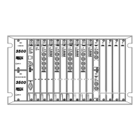
Attach the system to the frame using twelve 12-24 screws. Torque to 35 in-lb.

Step 2 - Connect Chassis and DC reference (CO) ground

Connect Chassis Ground

Connect chassis ground lug using #10 or 1/4" on 5/8" centers. Minimum 10 AWG recommended.

Connect DC Reference Ground

Connect DC reference ground lug - 5/16" or 3/8" on 1" centers. Torque to 160 in-lb.

Step 3 - Connect AC inputs

Connect AC Inputs to Rectifier Shelf

Connect 120/208/220VAC at rear of each rectifier shelf. Follow safety rules.

Step 4 - Connect Batteries and DC Output to Loads

Battery and DC Load Connections

Shows DC circuit, battery connections to bus, and load connections via breakers.

Step 5 - Set Controller alarm relay jumpers

Configure Pulsar Plus Alarm Relay Jumpers

Set jumpers 1-10 for alarm relays (Close/Open on Alarm). Factory default is Open.

Step 6 - Connect Controller Signals

Connect Pulsar Plus Controller Signals

Connect Pulsar Plus controller to J2, J3, J4, and J5 per site engineering.

Step 7 - Installation of Power Modules

Install Rectifier or Converter Modules

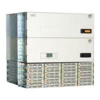
Slide power unit into slot, open faceplate latch, slide unit fully, close faceplate.

Step 8 - Initial Startup

Step 9 - Configure Controller

Information: AC Cord Options

Information: Battery Monitoring Connections

Battery Monitoring Setup

Daisy chain probes to J2 to monitor temp/voltage. Bolt probe under negative terminal connector.

Information: Battery Monitoring Cables

Information: Controller Connections

Controller Alarm Outputs

Factory set to Open On Alarm. J4 provides primary customer alarm outputs.

Controller Alarm Inputs

Default alarm descriptions can be changed. J4 is a 10-pin latching connector.

Information: Controller Basic Operation

Accessing Controller Parameters

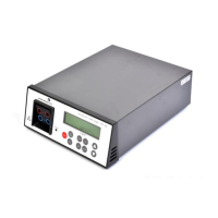
View/change parameters via display, craft port (EasyView2), or LAN port (web pages).

Controller Alarm Status and Clearing

Display colors indicate status. Clear alarms via menu path: Control/Operation > Clear Events.

Front Panel Controls

Front Panel Display and Controls

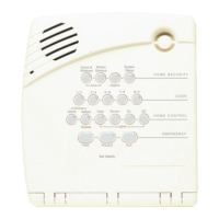
Overview of front panel display, navigation buttons, and menu access.

Controller Web Interface

Accessing Controller via LAN Port

Configure LAN port to SERVER mode, access web pages at 192.168.2.1. Use default password 'Administrator'.

Web Interface Overview

Displays Plant Status, Battery, and Plant Configuration. Change default password immediately.

Rectifier and Converter Specifications

Rectifier Status LEDs

Converter Status LEDs

Specifications and Application

Reference Documents

Safety Statements

General Safety Rules and Regulations

Follow national/local rules, use proper connectors, torque, cable dress, breakers, fuses.

Grounding and Protection

Connect chassis to ground, provide disconnects, alarm signals, and external current limiting.

Precautions for Servicing

Personnel and Tool Safety

Use insulated tools, remove metallic objects, follow LOTO, wear safety glasses, ESD strap.

Electrical Hazard Awareness

Test circuits, identify hazards, avoid live circuits, be aware of medical device effects.

Notes

Related product manuals