Revision B 6-19
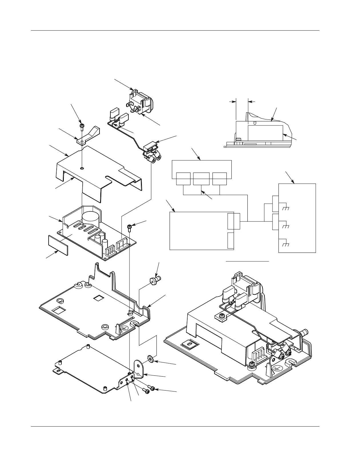
Parts Lists and Drawings: 421117-001A Power Supply Assembly
MAC 5000 resting ECG analysis system
2000657-002
11
8
6
Power Inlet
Connector J1
Power
Supply
PS1
J1L
Ground
Bracket
Ground
E1
Ground
E4
Ground
(BRN)
(GRN/YEL)
(BLU)
J1NJ1GND
W1E3
PS1J2
PS1J1
W1P1
W1E1 W1E4
W1E2W1E5
1
4
J1
Notes:
1. P1 end of Harness (Item 6) must be attached to Power Supply
(Item 7) prior to assembling Shield (Item 1).
2. Clear Liner on pink side of Thermal Pad to remain intact. Liner
is removed at final assembly.
3. Stamp Circle around Ground Symbol on Item 11 using MT-5098.
5 Ref
7 Ref
11 Ref
10 Ref
13.5
Power Supply
Heat Sink
E3-BRN
E2-BLU
E1
E4
E5-GRN/YEL
See Note 3
W1 See Note 3
4
Detail A
Wiring Schematic
3
5
9
4 PL
4
2 PL
Ground E1
Ground E4
2
7
PS1
10
See Detail A
See Note 2
This edge to fit
over top edge of
Thermal Pad (Item 10)

 Loading...


