Revision B 6-25
Parts Lists and Drawings: 900997-001C Trolley
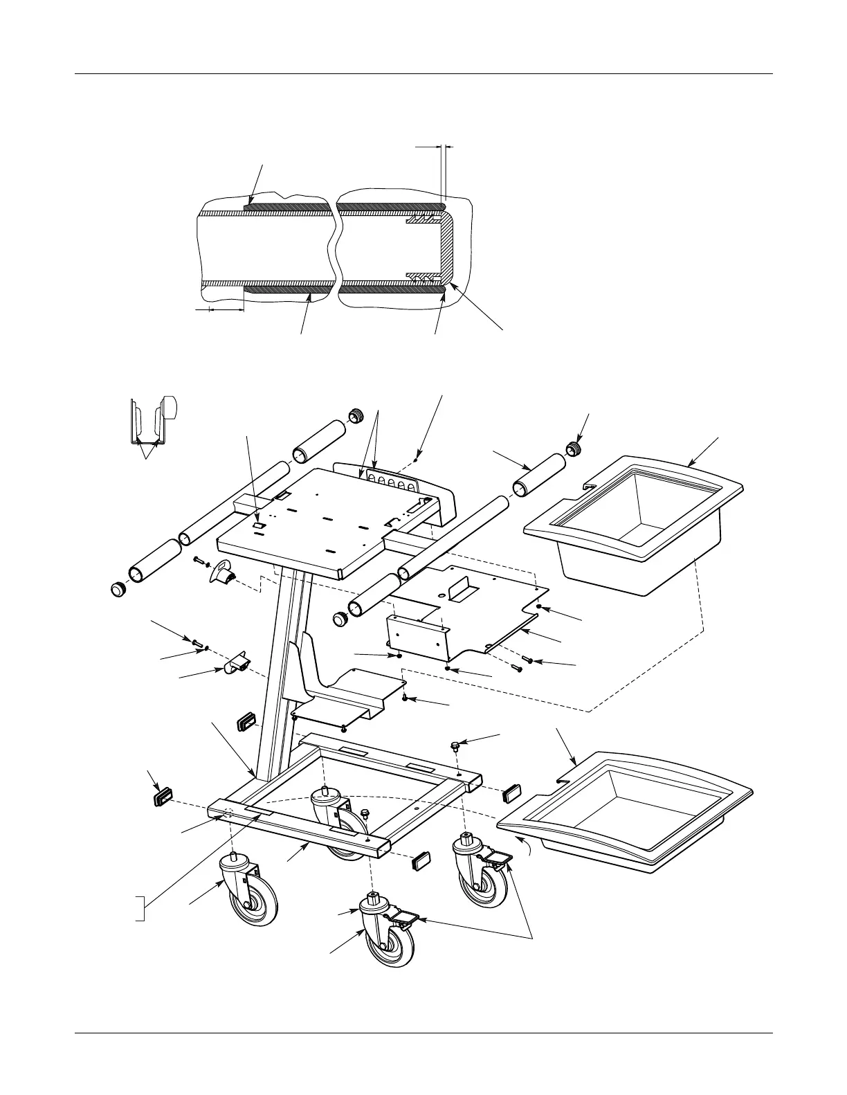
MAC 5000 resting ECG analysis system
2000657-002
Ground Tab Ref
See Note 5
12 PL (or use 6 different - Headed Screws where hidden)
Remove all
Plastic Burrs
4 PL
See Section A-A
5 PL
2 PL
Install Grip with
tapered end on first
To hide painted
surface of Tube
4 PL
Distance from Center
Post to Grip to be
visually similar 4 PL
Grip must not move or
rotate wafter installation
Notes:
1. Both Trolley & Trays must be clean & free of Dust &
Debris.
2. Trolley must roll straight & all Wheels must be within
1.76 MM (.069 inches) from floor.
3. See Sheet 2 for packaging instructions.
4. Torque tolerances are ±10% of specified torque value.
5. Trolley must pass the following continuity test:
Resistance between the Ground Tab and one of the
Welded-in Caster Nuts or any of 4 Caster Dust Aprons
must measure 1000 OHMS or less.
Note trimmed end
Remove all Plastic
Shavings after
installing Caplug-
Caplug must be flush
to .79 from end of Tube
4 PL
+1.00
–0.00
View from
end of Tray
Orient Pad Assemblies
so thicker section
is on bottom
11
15
4
7
8
3
Section A-A
Cut trough Handle
4 PL
2 PL
2 PL
2 PL
After Lower Tray is installed
visible portion of Weld to
be of consistent size
2
5
9
6
3
3
10
13
2 PL
Release
Dust Apron
See Note 5
Welded-in
Caster Nut
2 PL See Note 5
Pound Endcap on
flush to .51 from
end of Tube-remove
all Plastic Burrs 4 PL
Apply Hook Fasteners to
Frame with Hook side up
then apply Loop Fasteners
to exposed Hook sides
remove backing of Loop
Fasteners & attach lower
Tray 4 PL each
Release Wheel Lock
on both Casters
before shipping
12
19
20
18
17
13
14
1
2.00

 Loading...


