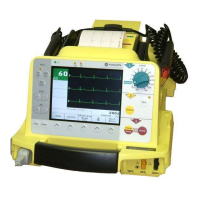
Putting the Device Into Operation and Performance Check
227 490 02-C Marquette Responder® 3000 13
ECG
ECG
Electrode
15.07.1999 09:05:00
160 / 40
bpm
SpO2
etCO2
QRSPulse
Tone
OFF
Next
Menu
semiautom.
0
Paddle
SpO2
parameter
window
etCO2
parameter
window
pacemaker
window
g
a fedcb
Figure 3-3. Standard screen display
a measured heart rate/pulse rate
b selected limit values
c battery charge level indication
d ECG lead (ECG signal acquired
via "Paddle")
e date, time
f selected operating mode,
defibrillation energy
g menu
The Standard Screen Display
This is the information presented on the standard
screen display:
−
windows for heart / pulse rate, SpO
2
and etCO
2
readings including the limit values
a
,
b
−
battery charge level
c
−
ECG lead
d
−
window for ECG, SpO
2
and etCO
2
waveforms
−
window indicating operating mode and
defibrillation energy
f
−
date and time
e
−
menu
g
.
The color concept for the displayed information
lets you see at a glance whether
−
the parameter reading is within the alarm limits
(green),
−
a technical fault is reported (blue),
−
an alarm is reported (red),
−
the system displays a message (yellow).
If the device does not receive an ECG signal, the
HR window is blue (technical fault) and a
sawtooth signal is displayed instead of an ECG.
The SpO
2
and etCO
2
parameter windows are also
blank and the corresponding waveforms are
missing when the required sensors are not
connected.

 Loading...