Displaying and Monitoring the ECG
227 490 02-C Marquette Responder® 3000 41
R L
C
N F
red
white
black
yellow
green
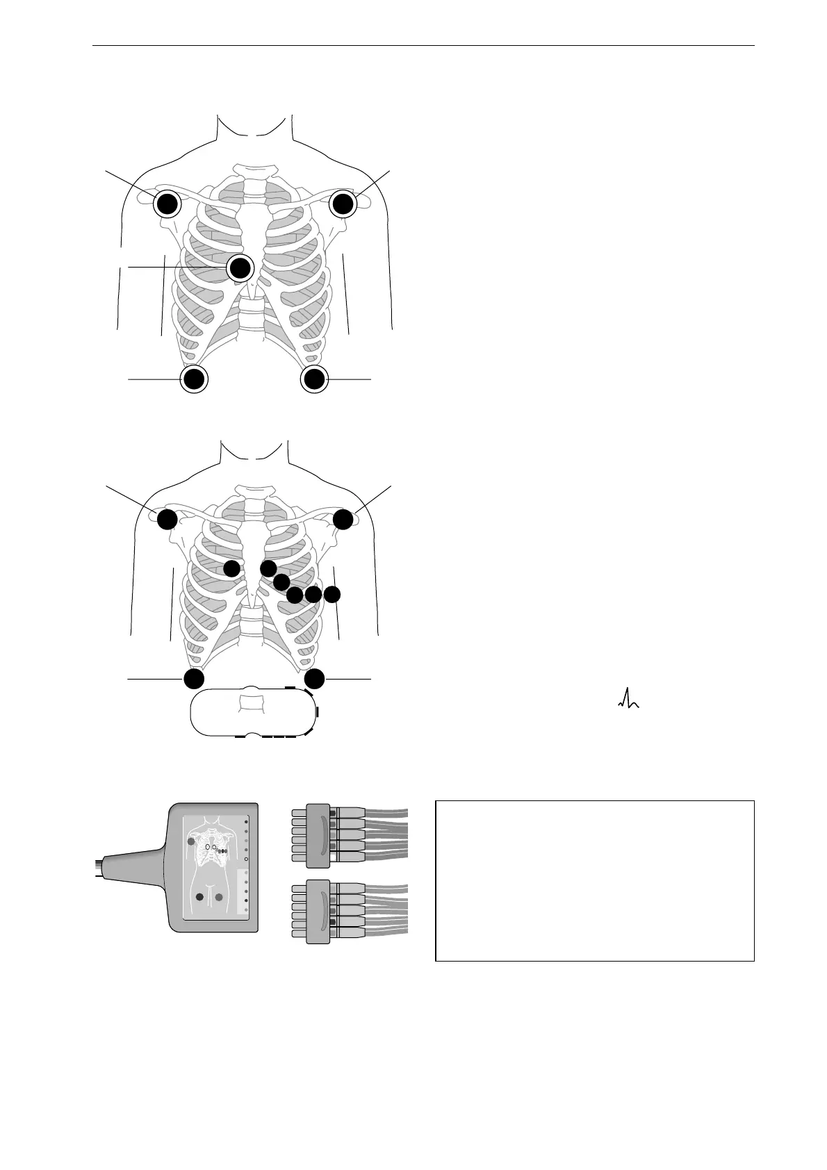
Figure 7-1. Signal acquisition with 5 electrodes
R L
N F
red
black
yellow
green
C1
C8
C7
C6
C1 C3C4
C5
C2
C2
C3
C4 C5 C6
Figure 7-2. Chest electrode placement
R
F
N
1
L
L
F
C
C1
R
N
2
3
4
5
6
C4
C5
C6
C3
C2
Figure 7-3. Connecting the leadwires to the
patient cable
7 Displaying and Monitoring the
ECG
Displaying the ECG
For a quick diagnosis of the ECG, you can use the
defibrillation electrodes (paddles) to acquire the
ECG.
For in-depth examinations and heart rate monitor-
ing, the ECG signal should be acquired via
separate ECG electrodes. Five or 10 ECG
electrodes can be applied to the patient. Ten
electrodes are required for the 12SL measurement
and interpretation program. Use silver/silver
chloride electrodes, if possible. Otherwise the
polarization voltages caused by the defibrillation
shock could simulate cardiac arrest.
•
If you are using only 5 electrodes, apply them
as shown in Figure 7-1. When working with 10
electrodes, additionally apply all chest elec-
trodes as shown in Figure 7-2.
•
Connect one (5 electrodes) or both leadwire
blocks to the patient cable (Figure 7-3).
Ensure that all leadwires are always connected.
Otherwise the connector of the leadwire may come
in contact with conductive parts and cancel the
protection provided by the isolated patient input.
•
Set the energy selector to .
After the test screen, the standard screen display
will appear (Figure 7-4), showing leads I, II and III
(factory defaults).
Note
−
ECG lead II is used for analysis and for cal-
culation of the heart rate. If lead II is not
available, the first suitable ECG lead displayed
will be selected.
−
The 3-lead patient cable cannot be used with
this defibrillator.

 Loading...


