Capnometry (etCO
2
)
54 Marquette Responder® 3000 227 490 02-C
CO
2
ADAPTER
OPER/ALARM
!
a
b
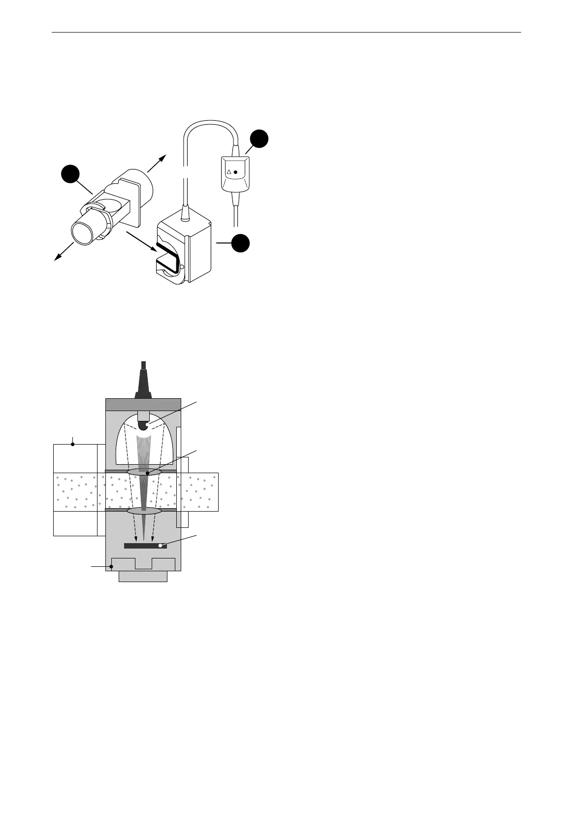
c
Figure 10-1. CO
2
sensor and airway adapter
a airway adapter
b sensor
c adapter cable
Infrared
light source
No-fog
membrane
Filter
(4.3 µm)
Airway
adapter
Detector
Figure 10-2. Principle of operation
10 Capnometry (etCO
2
)
Some Basic Facts
The etCO
2
sensor uses the infrared spectroscopy
method. The sensor consists of the sensor itself
b
(including the IR source and the photodetector) and
the airway adapter
a
which is attached to the sensor.
The entire sensor is placed in the patient's airway
(expired air) between the respirator and the tube. The
airway adapter is for single use only. It must not be
reused (Figure 10-1). The etCO
2
value is given in
mmHg and can be monitored. A capnogram
waveform can be displayed on the screen.
Principle of Operation
The method of infrared spectroscopy is based on the
fact that the CO
2
gas in the patient's expired air
absorbs infrared light at specific wavelengths. The
absorbed amount of light is in proportion with the
amount of CO
2
in the respired air. A "No-fog-
membrane" ensures that no condensation collects on
the sensor (Figure 10-2). The method used is a
semi-quantitative measuring method and it is
assumed that the inspired air is free of CO
2
.
etCO
2
Monitoring Literature
Falk J L, Rackow E C, Weil M H (1988) End-tidal carbon
dioxide concentration during cardiopulmonary resuscita-
tion. New Engl J Med 318: 607-611
MacLeod B A, Heller M B, Gerard J et al. (1991) Verification
of endotracheal tube placement with colorimetric end-tidal CO
2
detection. Ann Emerg Med 20: 267-270
Sanders A B, Kern K B, Otto C W (1998) End-tidal carbon
dioxide monitoring during CPR: A prognostic indicator for
survival. JAMA 262: 1347-1351
White R D, Asplin B R (1994) Out-of-hospital quantitative
monitoring of end-tidal carbon dioxide pressure during
CPR. Ann Emerg Med 23: 25-29
Bhavani-Shankar K; Mosley H; Kumar Y Y (1992)
Capnometry and anaesthesia (Review Article). Can. J.
Anaesth. 39: 617-632

 Loading...


