Capnometry (etCO
2
)
56 Marquette Responder® 3000 227 490 02-C
a
c
b
d
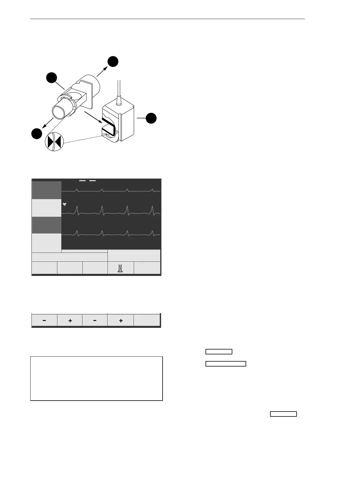
Figure 10-3. Attaching the airway adapter
ECG
ECG
I
II
III
15.07.1998 09:05:00
160 / 40
bpm
etCO2
SpO2
QRSPulse
Tone
OFF
Next
Menu
semiautom.
89
etCO2
---
20
mmHg
37
Figure 10-4. etCO
2
reading
Previous
Menu
High
etCO2
AlarmLow
etCO2
Alarm
Figure 10-5. Alarm limits menu
Note
etCO
2
alarms are similar to HR alarms. Please
refer to chapter 7 "Displaying and Monitoring the
ECG".
Measuring and Monitoring etCO
2
•
Obtain a new airway adapter and check that the
windows are intact and clean.
•
Attach the airway adapter to the sensor (the
triangles on the airway adapter and on the
sensor must be in alignment - Figure 10-3).
•
Connect the airway adapter to the respirator
system (connector
c
towards the patient, con-
nector
d
towards the respirator - Figure 10-3).
•
Ensure that the sensor is on top and that the
windows of the airway adapter are in a vertical
position. Although the "No-fog-membrane"
prevents moisture condensation on the window,
liquid secretions could soil the window.
•
Connect the sensor to the defibrillator (yellow
connector, right).
The CO
2
measurement begins as soon as the sensor
is connected. During the short self-test, the
parameter window is blue. As soon as the sensor
supplies a valid reading, the color changes to
green. Check that the indicator on the CO
2
adapter
cable lights green; if a problem is detected, the
indicator flashes red (apnea or system failure).
At the factory, only a low etCO
2
limit of 20 mmHg
is adjusted, no high limit. When the parameter
reading drops below this value, the defibrillator
sounds an alarm and the window changes from
green to red.
Adjusting Alarm Limits
The alarm limits can be modified permanently
from the setup menu or temporarily as described
below:
•
Press
F2
SpO2 etCO2
.
•
Press
F1
etCO2 Alarm Limits
to display the alarm
limits menu (Figure 10-5).
•
Change the high limit with
F1
,
F2
and the low
limit with
F3
,
F4
.
•
To deactivate the etCO
2
measurement, remove
the sensor connector and press
F2
SpO2 etCO2
.

 Loading...


