Battery Power Operation
68 Marquette Responder® 3000 227 490 02-C
I
II
III
ECG
ECG
Electrode
15.07.1999 09:05:00
160 / 40
bpm
SpO2
etCO2
QRSPulse
Tone
OFF
Next
Menu
semiautom.
62
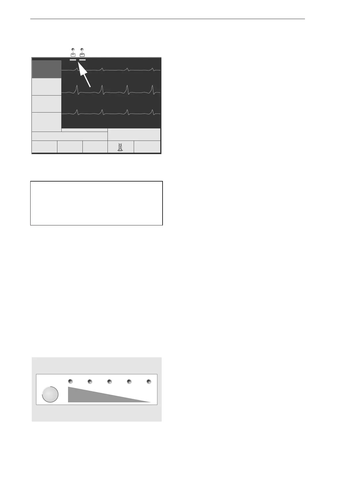
Figure 14-2. Battery charge level indicators
Note
The battery on the left is the working battery, the
one on the right the spare battery. Exchange the
batteries on a monthly basis.
Test
Figure 14-3. Battery test button and charge
indicators
Information on Battery Power Operation
Rechargeable batteries require special maintenance
and continued checks to assure they function in
emergency situations. It is normal for batteries of
this type to self-discharge, even when the device is
switched off. Furthermore, the capacity decreases
with age.
By regular maintenance (charging and discharging
at regular intervals) the battery service life can be
considerably extended. The defibrillator as well as
the separate charging unit ASU 3000 have a
special battery maintenance program (see next
section).
To ensure that the Marquette Responder® 3000 will
always function in an emergency, it must not be
disconnected from an external power source for
more than 48 hours (mains or ambulance power
supply). Reconnect the defibrillator to the external
power source immediately after use or recharge the
batteries with the separate charging unit. The batteries
cannot be overcharged.
The two horizontal bars in the upper margin of the
screen (Figure 14-2) continuously indicate the
battery charge level:
green: battery full (40 to 100%)
yellow: medium charge level (20 to 40%)
red: battery depleted (0 to 20%)
If two batteries are inserted, they will be dis-
charged one after the other, not at the same time.
The battery charge level can be checked by
pressing the
Test
button (Figure 14-3) on the
battery (for this test, the battery does not have to
be inserted in the defibrillator).
5 LEDs: charge level between 80 and 100%
4 LEDs: charge level between 60 and 80%
3 LEDs: charge level between 40 and 60%
2 LEDs: charge level between 20 and 40%
1 LED: charge level between 0 and 20%
no LED: battery depleted

 Loading...


