Technical Specifications
80 Marquette Responder® 3000 227 490 02-C
ECG Signal Input Via Patient Cable
automatic switching to ECG electrodes, if they are
applied;
differential input, symmetrically referred to N,
isolated, IEC class CF;
7 standard leads via lead selector; input overvolt-
age protected (defibrillation-proof):
•
input voltage range ±10 mV for recorder and
display
•
input impedance > 10 MOhms for 10 Hz
•
common-mode dynamic range ±1 V
•
differential DC voltage tolerance ± 0.6 V
•
common-mode rejection (CMRR) RL referred
to N > 65 dB, N referred to chassis > 110 dB
•
band width 0.15 to 100 Hz,
with 12 SL 0.08 to 100 Hz
•
patient leakage current: in normal condition <
10 µA, in single-fault condition < 50 µA
•
ground leakage currents: in normal condition <
0.5 µA, in single-fault condition < 1 µA
•
voltage resistance referred to ground reference
3 kV (static)
•
detection of pacing pulses
−
pulse duration d
p
> approx. 0.1 ms < 2.0 ms
−
pace marker independent of polarity
−
pulse amplitude a
p
± 10 to ± 700 mV
−
reverse current pulse a
0
± 1 mV
−
time constant t
0
= 25 to 100 ms
−
overall error < 20 % (typical)
Signal Transmission
signal input --> amplification --> signal sampling -
-> AD conversion --> digital processing -->
display and recorder
•
adjustable gain: 0.5
– 1 – 2 cm/mV (with max.
gain a 1-mV input signal results in 2 cm/mV)
•
amplitude limited to the area of the waveform
window on the display and to the recorder
writing width
•
signal sampling rate of 1000 Hz (reduction to
400 Hz)
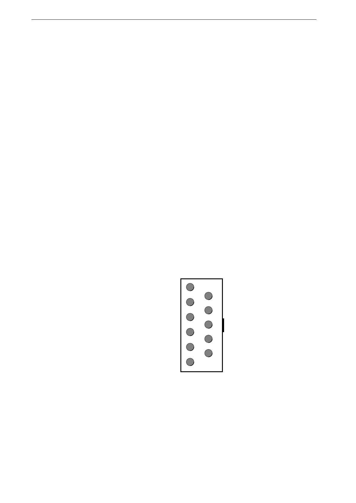
ECG Signal Output ("Option" port)
•
ECG lead shown in channel 1 on the display
•
1 V output signal for 1 mV input signal
•
U
max
±2 V
•
overall error < 3% (typical)
•
R
L
500
Ω
min.
•
delay < 150 ms (not suitable for triggering of
external devices)
•
no electric isolation
7
8
9
10
11
1
2
3
4
5
6
9 = ECG
10 = chassis
Only connect devices that meet
the requirements of EN 60601-
1 and EN 60601-1-1,
respectively.

 Loading...


