7 | GE Oil & Gas © 2015 General Electric Company. All rights reserved.
Ref.
No.
Description
Ref.
No.
Description
Ref.
No.
Description
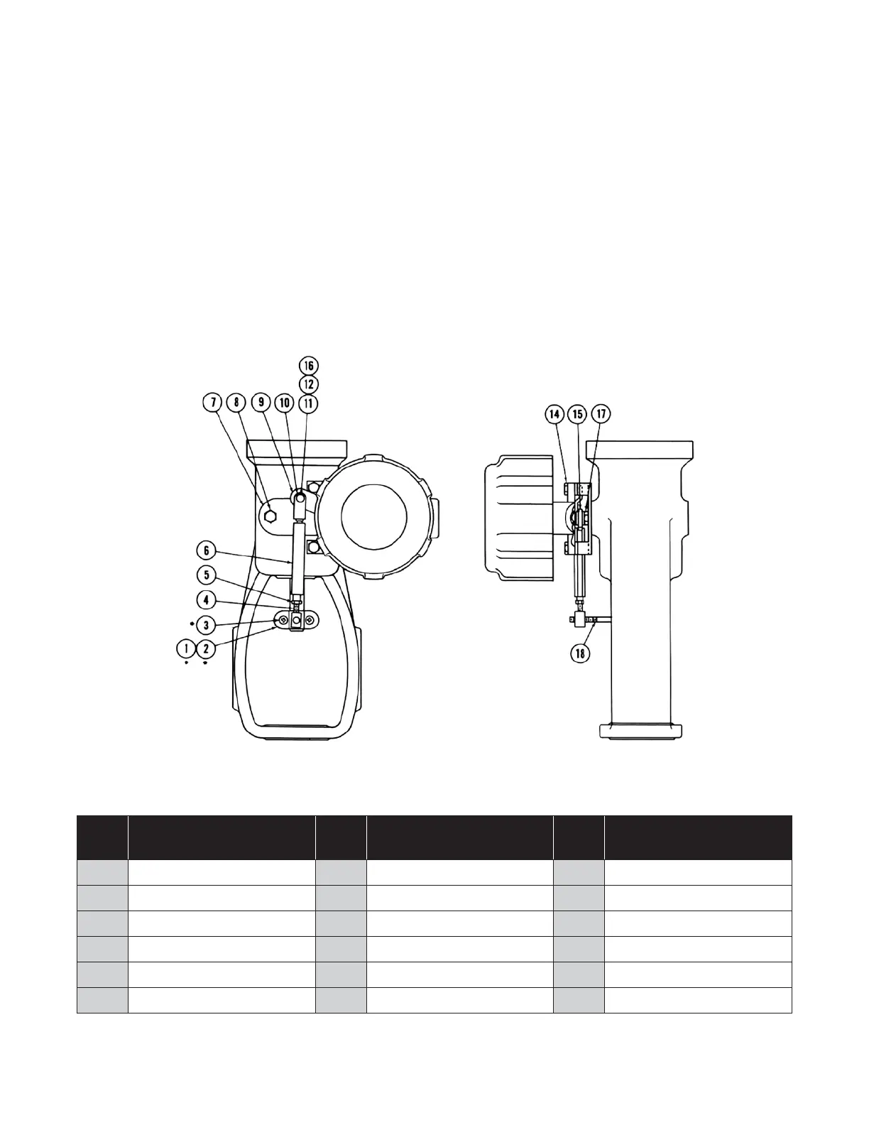
*1 Clamp 7 Mounting Bracket 14 Cap Screw
*2 Clamp 8 Cap Screw 15 Spring Washer
*3 Machine Screw 9 Back Lever 16 Washer
4 Turnbuckle Screw 10 Clevis 17 Cap Screw
5 Locknut 11 Clip 18 Clamp Rod
6 Turnbuckle 12 Pin
*Used with size 9, 11 and 13 actuators only.
Figure 6
37/38 Spring Diaphragm Actuator
C. 37/38 Diaphragm Actuators
The 496 switch is rigidly mounted on the spring barrel of the
diaphragm actuator by means of a bracket (7) fastened to
the mounting pad with cap screws (8). The back lever (9) is
fastened to the end of the switch shaft with spring washer
(15) and cap screw (17).
The take off linkage must be adjusted before adjusting the
switches. Apply air pressure to the actuator until the actuator
stem has traveled exactly half the rated stroke. Loosen
locknut (5) and turn the turnbuckle (6) until the back lever (9)
is level. Tighten locknut (5) and adjust switches according to
instructions on Page 2.
 Loading...