3 | GE Oil & Gas © 2015 General Electric Company. All rights reserved.
3
1
/
16
2
11
/
16
3
15
/
16
5
/
16
15
/
16
2
13
/
16
2
3
/
4
5
3
/
8
3
/
4
NPT
2
9
/
16
1
9
/
16
8 Mounting
Holes
17
/
64 D A
Cover
Removal
Clearance
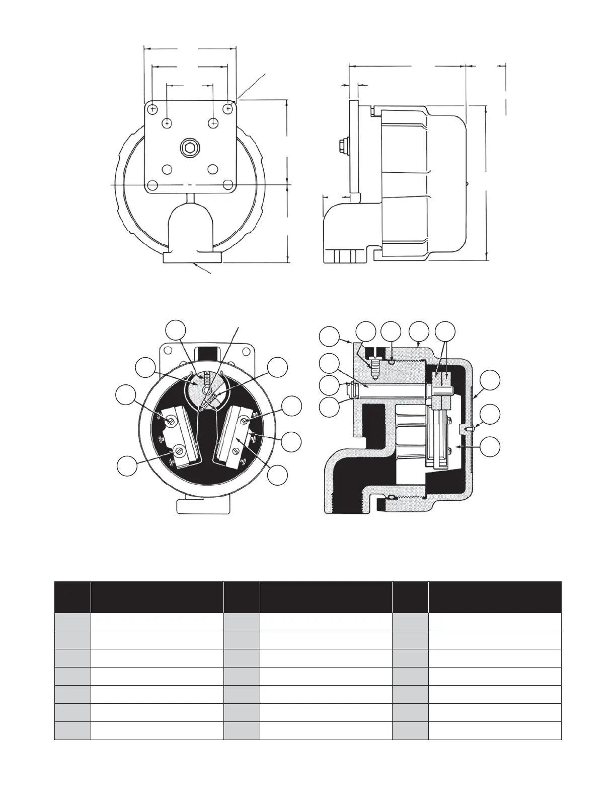
Figure 1
Dimensions
Contact Points
17
13
1
2
4
5
6
9 10 12 13
14
15
16
11
8
7
18
3
Ref.
No.
Description
Ref.
No.
Description
Ref.
No.
Description
1 Screw 8 Snap Ring 14 Serial Plate
2 Screw 9 Screw 15 Drive Screw
3 Screw 10 O-Ring 16 Insulator
4 Microswitch 11 Shaft 17 Screw
5 Lever 12 Cover 18 Washer
6 Body 13 Cam 19 Spacer (not shown)
7 O-Ring
Figure 1
Dimensions
Figure 2
Cutaway Views
 Loading...