APPENDIX I — 269 Commissioning Summary 269.D6.0.4
I-2
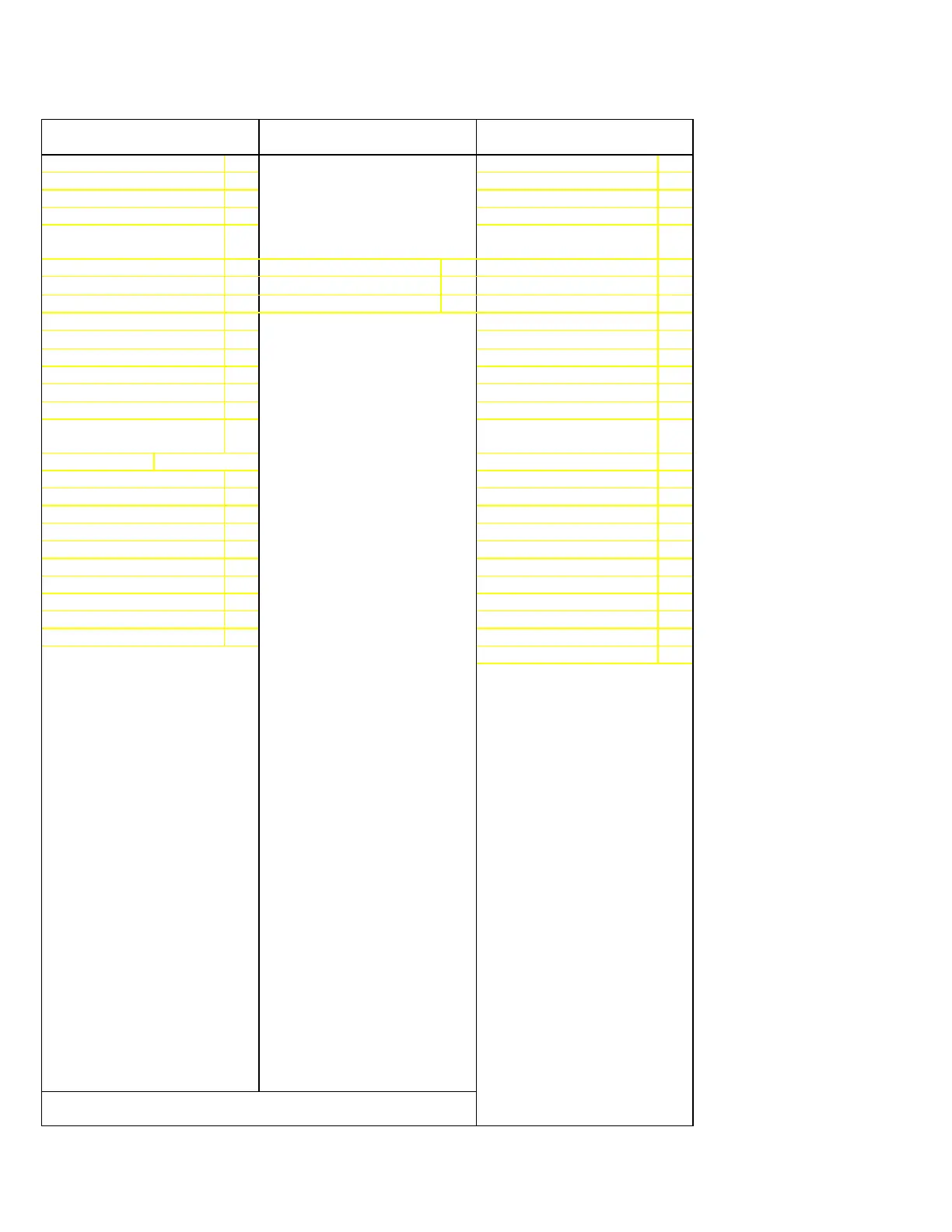
PAGE 5: SETPOINT VALUES
SYSTEM CONFIGURATION
PAGE 6: SETPOINT VALUES
MULTILIN SERVICE CODES
PAGE 7: SETPOINT VALUES
METERING SETPOINTS
Norm Run Disp Line Setpoints Set/On Line?
Norm Run Disp Page Meter CT Primary (amps)
Defeat No Sensor Alarm
4
Applicable for Service V.T. Ratio
Enable Low Temp. Alarm
4
Application Only. Meter VT Secondary (V)
Enable Stator RTD
Voting
4
U/V Trip/Alarm Avg V=0?
Defeat RTD Input
4
Place 269 in test mode? U/V Alarm Level (%VT)
RTD Bias Curve Min (°C)
5
Software Access U/V Alarm Delay (sec)
RTD Bias Center (%)
5
Encrypted Code U/V Trip Level (%VT)
RTD Bias Center Temp(°C)
5
U/V Trip Delay (sec)
RTD Bias Curve Max (°C)
5
O/V Alarm Level (%VT)
Defeat Unbalance Input O/V Alarm Delay (sec)
Default K Value
6
O/V Trip Level (%VT)
Running Cool Time (min) O/V Trip Delay (sec)
Stopped Cool Time (min) Block PF Prot. on Start
RTD 8 Ambient Sensor
4
PF Protection Delay
(sec)
8
Analog Output Blk PF Alm/Trip by (sec)
9
Analog Output Type PF Lead Alarm Level
Motor Load Anlg.Output FS
PF Lag Alarm Level
Relay Alarm Latchcode PF Alarm Delay (sec)
Drawout Failsafe Code
7
PF Lead Trip Level
Relay Failsafe Code PF Lag Trip Level
Sp. Inp. to Read 52B? PF Trip Delay (sec)
Time Between Starts (min)
Pos KVAR Alarm Level
FLC Therm. Cap. Red. (%)
Neg KVAR Alarm Level
TC Used Alarm Level (%) KVAR Alarm Delay
TC Used Alarm Delay (sec)
Voltage Phase Rev.?
Scale Factor
4
Not seen if no RTDs are
8
Not seen if “Block PF Protection
connected (see note 3) on Start” is YES
5
Not seen if “Defeat RTD Input” is
9
Not seen if “Block PF Protection
YES on Start” is NO
6
Not seen if “Defeat U/B Input” is
YES
7
Only seen if 269 is a drawout relay
NOTE: Shaded setpoints in commissioning summary have
been added or altered as compared to last revision

 Loading...


