3 SETUP AND USE
No. Name Description
3-5
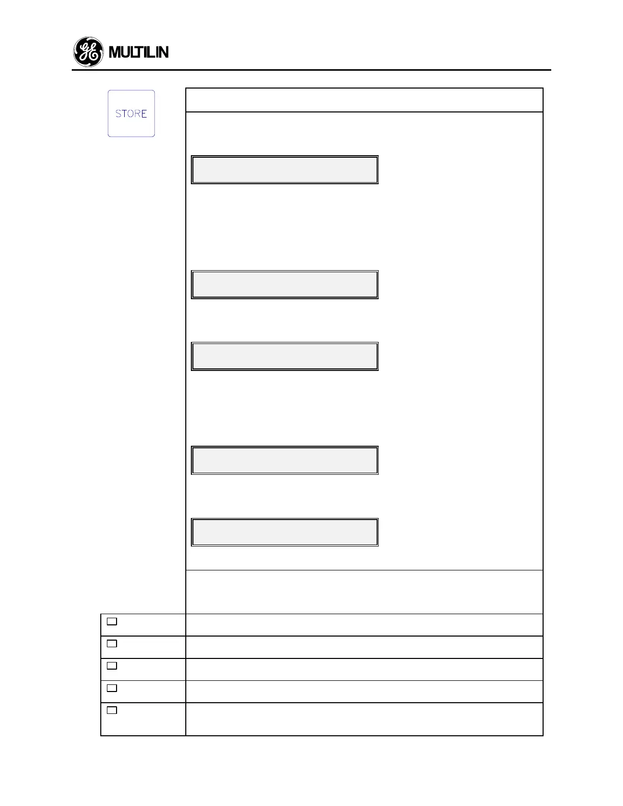
12 FUNCTION: The STORE key allows the user to store new setpoints into the 269
relay's internal memory.
EFFECT: When this key is pressed in SETPOINTS mode the currently displayed
setpoint will be stored and will immediately come into effect. When a setpoint is
stored the flash message,
NEW SETPOINT STOREDNEW SETPOINT STORED
will appear on the display.
The STORE key can be pressed in ACTUAL VALUES mode to clear the maximum
actual temperature data. To do this the following message from page 2 of ACTUAL
VALUES mode must be displayed after the "NO" value is altered to say "YES" by
pressing the VALUE UP/VALUE DOWN key:
CLEAR LAST ACCESS DATA?CLEAR LAST ACCESS DATA?
YESYES
Then when the STORE key is pressed the following flash message will appear on
the display:
last access data clearedlast access data cleared
The maximum actual temperature data (see section 3.24) will then be cleared. The
STORE key can be pressed in ACTUAL VALUES mode to start a new motor com-
missioning (ie. clear statistical data). To do this the following message from page 4
of ACTUAL VALUES mode must be displayed after the "NO" value is altered to say
"YES" by pressing the VALUE UP/VALUE DOWN key:
START COMMISSIONING?START COMMISSIONING?
YESYES
Then when the STORE key is pressed the following flash message will appear on
the display:
COMMISSIONING DATACOMMISSIONING DATA
clearedcleared
All statistical data (see section 3.24) will then be cleared.
USE: The STORE key can be used only in SETPOINTS mode to store new set-
points, or in ACTUAL VALUES mode to clear the maximum actual temperature data
or start a new commissioning (ie. clear statistical data). This key will have no effect
unless the Access terminals are shorted together.
13
TRIP
LED indicator used to show the state of the Trip output relay. When on, the trip
relay is active. When off, the Trip relay is inactive.
14
ALARM
LED indicator used to show the state of the Alarm output relay. When on, the Alarm
relay is active. When off, the Alarm relay is inactive.
15
AUX. 1
LED indicator used to show the state of Auxiliary relay #1. When on, Aux. relay #1
is active. When off, Aux. relay #1 is inactive.
16
AUX. 2
LED indicator used to show the state of Auxiliary relay #2. When on, Aux. relay #2
is active. When off, Aux. relay #2 is inactive.
17
SERVICE
LED indicator used to show the result of the 269 self-test feature. When flashing,
the relay has failed the self-test and service is required. When on steady, the supply
voltage may be too low. This LED may be on momentarily during relay power up.

 Loading...


