3 SETUP AND USE
3-60
the relays, motor and associated equipment. Under
such circumstances, the power factor measured by the
MPM and displayed by the 269 appears to be swinging
from a very low lagging value to a very low leading
value with the field being constant. This may mislead
you to believe that wiring problems such as reversed
CT or VT polarities or wrong connections exist. More
often than not however, there is nothing wrong with the
wiring. In order to understand why the displayed power
factor is swinging from lead to lag, it is important to
understand how power factor is determined and why
power factor is not the best indication of proper opera-
tion and wiring when the motor is unloaded and the
field applied. Recommendations will be made for com-
missioning and checking for wiring problems.
THE PHENOMENON
By convention, an induction motor consumes watts and
vars. This is shown in the 269 as positive watts and
positive vars. A synchronous motor can consume watts
and vars or consume watts and generate vars. This is
shown in the 269 as positive watts, positive vars and
positive watts, negative vars respectively. See Figure
3.7.
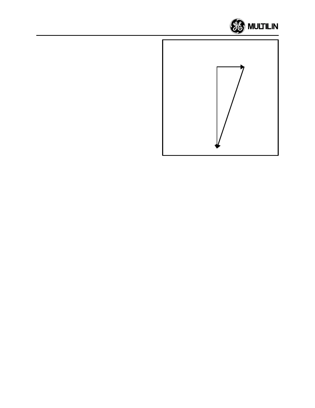
Since the motor is unloaded, the real power or kW re-
quired to run the machine is at its minimum. The reac-
tive power or kvar is a function of the field and motor
requirement, and is at a high value with the field ap-
plied. In fact the motor will be running extremely over-
excited. The apparent power or kVA is the vector sum
of both kW and kvar as seen in Figure 3.8, and hence it
is at a high value with the field applied. The result is a
power factor that is significantly low with PF = kW/kVA
(low value/high value). Because of these unrealistic
motor conditions, and because of digital technology of
sampling waveforms, it is possible that the PF sign is
detected to be either leading or lagging. This is clearly
seen in Figure 3.7 where at around 270°, the PF is very
low and changes signs with the slightest movement
around this angle in either direction.
kvar
kW
kVA
Figure 3.8
RECOMMENDATIONS
By examining Figure 3.7, it is very obvious that the only
stable and reliable number that should be checked on
commissioning of unloaded synchronous motors with
the field applied is the signed REACTIVE POWER or
kvar. Under such circumstances the kvar number
should always be NEGATIVE with a value that is sig-
nificantly larger than that of the real power or kW.
Glancing at the kW number, it should be a very small
value with possible fluctuations in the sign from positive
to negative. By examining the apparent power or kVA
number, it should always be positive and also relatively
large, almost equal to the kvar number. Consequently,
the PF number will be a very small value in the order of
0.02 to 0.2, also with a possible unstable sign going
from leading to lagging.
Once the kvar value is examined and found to be in-
consistent with the observations made above, it could
be safely assumed that there may be some wiring
problems in the switchgear. It is important however, not
to ignore the other values, because if the kW value is
examined and found to be a large number, regardless
of its sign, it is also an indication of wiring problems.
Similarly, a large value for the PF, regardless of its sign
is an indication of wiring problems.

 Loading...


