5-8 F650 Digital Bay Controller GEK-113000T
5.2 BOOT CODE UPGRADE 5 BOOTCODE AND FIRMWARE UPGRADE
5
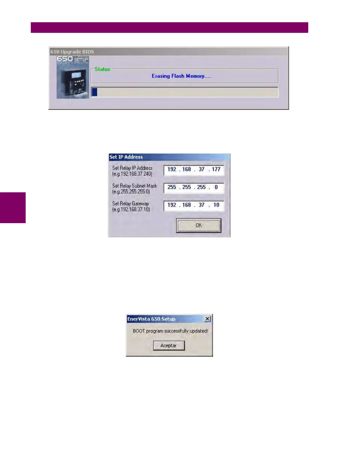
Figure 5–13: ERASING FLASH MEMORY
Once the memory has been erased and the files upgraded in the relay, the parameters for the Ethernet communications
must be set (Figure 5–14:). The requested values are the IP address and the gateway
Figure 5–14: ETHERNET PARAMETERS
These values should match the LAN structure in which the relay will be connected.
The gateway must be the one used in the LAN structure connecting the relay. The relay IP address should have the first
three octets corresponding with the Gateway and the last octet must be a free IP address reserved to the relay to avoid
possible collisions with other devices.
After assigning the Ethernet parameters, the upgrade of the boot code has been completed successfully (Figure 5–15:).
Figure 5–15: BOOT PROGRAM UPGRADED
After boot code upgrade, the equipment firmware must also be upgraded (Section 5.3).

 Loading...


