Do you have a question about the GE NX-148E-RF and is the answer not in the manual?
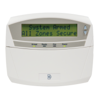
Guidelines for mounting the touchpad, including distance, environment, and clearance.
List of tools and supplies required for installing the touchpad and receiver.
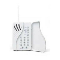
Guidelines for programming wireless transmitters with the touchpad receiver.
Overview of transmitter programming options and partitions.
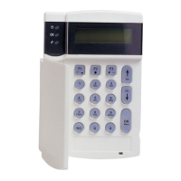
Procedure to set the touchpad's unique number and assigned partition.
Step-by-step instructions for learning new transmitters into the touchpad receiver.
Configuring transmitter options, keyfob partitions, and supervision windows.
Deleting transmitters and performing functional testing and troubleshooting.
Adjusting tone, master mode, viewing status, service menu, and alarm memory.
Performing system tests, including battery, communicator, and display tests.
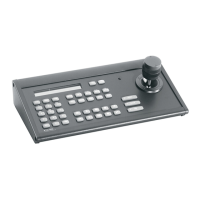
Controlling and configuring X10 devices using light control and unit/house codes.
Managing user authority, codes, system resets, and reviewing the event log.
Adjusting LCD brightness and changing the touchpad's display language.
Creating and transferring custom text messages to the touchpad.
Setting features like silent operation, chime, and display behavior.
Configuring autotest intervals and setting the system time and date.
Initiating remote downloads and managing phone line seizure.
Testing zone functionality with walk tests and enabling silent exit.
Technical details including frequency, range, power, and dimensions.
Regulatory compliance statements regarding FCC rules and operation.
| power requirements | 12.0 VDC (provided by panel) |
|---|---|
| current draw | 75 mA maximum |
| operating temperature | 32° to 120°F (0° to 49°C) |
|---|---|
| storage temperature | -30° to 140°F (-34° to 60°C) |
| humidity | 90% relative, non-condensing |
| frequency | 319.5 MHz |
|---|---|
| wireless range | 600 feet (183 m) open air |
| dimensions | 5 x 6 x 1 in. (12.7 x 15.2 x 2.5 cm) |
|---|