13 Technical Specifications
2 TECHNICAL SPECIFICATION
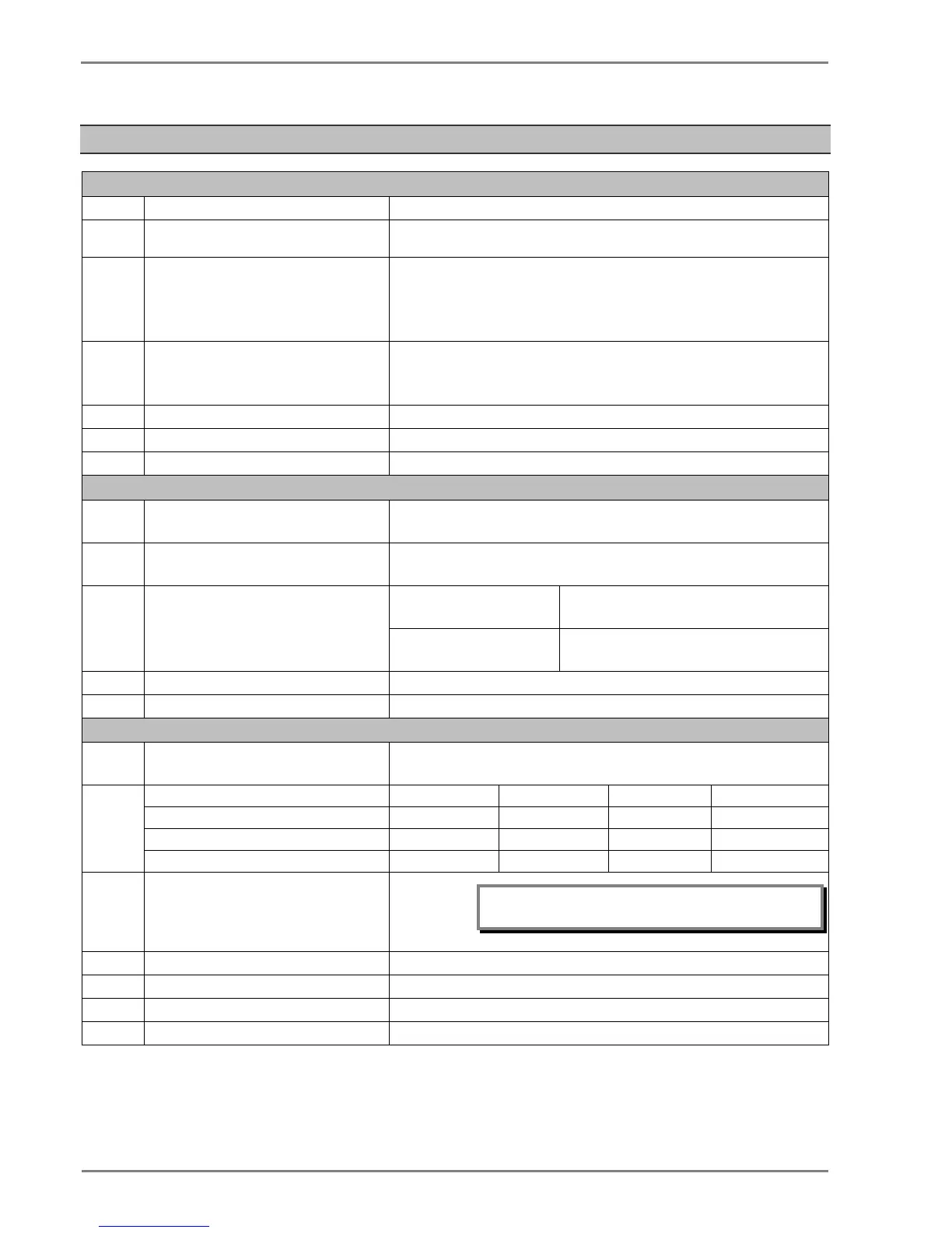
Current Input
I.
CT secondary 1 A or 5 A (by wiring)
II.
Nominal burden at rated current (without
tripping condition)
< 0.20 VA at rated current (In)
III.
Thermal withstand capacity 100 x rated current (In) for 1s
50 x rated current (In) for 3s
4 x rated current (In) continuous for Phase and E/F CT
2 x rated current (In) continuous for SEF CT
IV.
Measurement linearity range
(for non – offset AC current)
For O/C : 0.05 – 40 In
For E/F : 0.05 – 40 In
For SEF : 0.002 – 4.0 In
V.
Typical ± 2% at In for Phase and EF CTs
Nominal frequency range for current Inputs
50/60 Hz (selectable in P253 Menu)
Frequency measurement range
Auxiliary Supply
I.
Nominal auxiliary voltage 24-230 V AC (50 / 60 Hz) or
24-230 V DC
II.
80% of lower nominal range and 120% of upper nominal range for DC supply
80% of lower nominal range and 110% of upper nominal range for AC supply
III.
Nominal burden on 24 – 230 V auxiliary power
< 10 VA (no status energized)
< 13 VA (with all status and output energised)
< 3 W (no status energized)
< 4.5 W (with all status and output energised)
Tolerable ac ripple Up to 15% of highest dc supply, as per IEC 60255-26: 2013
Relay power-up time < 2.50s
Opto Isolated Input
I.
Nominal operating voltage range
24-230 V AC (50 / 60 Hz) or
24-230 V DC
II.
Threshold setting (ordering option)
Maximum operating voltage range
*Note: The 24/30V inputs must be connected via
screened cable or twisted pair cable.
III.
Within 85% of threshold voltage value
For each status < 1.5 W / VA
V.
Filtering time < 40 ms
VI.
Logic input recognition time
For all status inputs: filtering time + 5ms ± 5 ms

 Loading...


