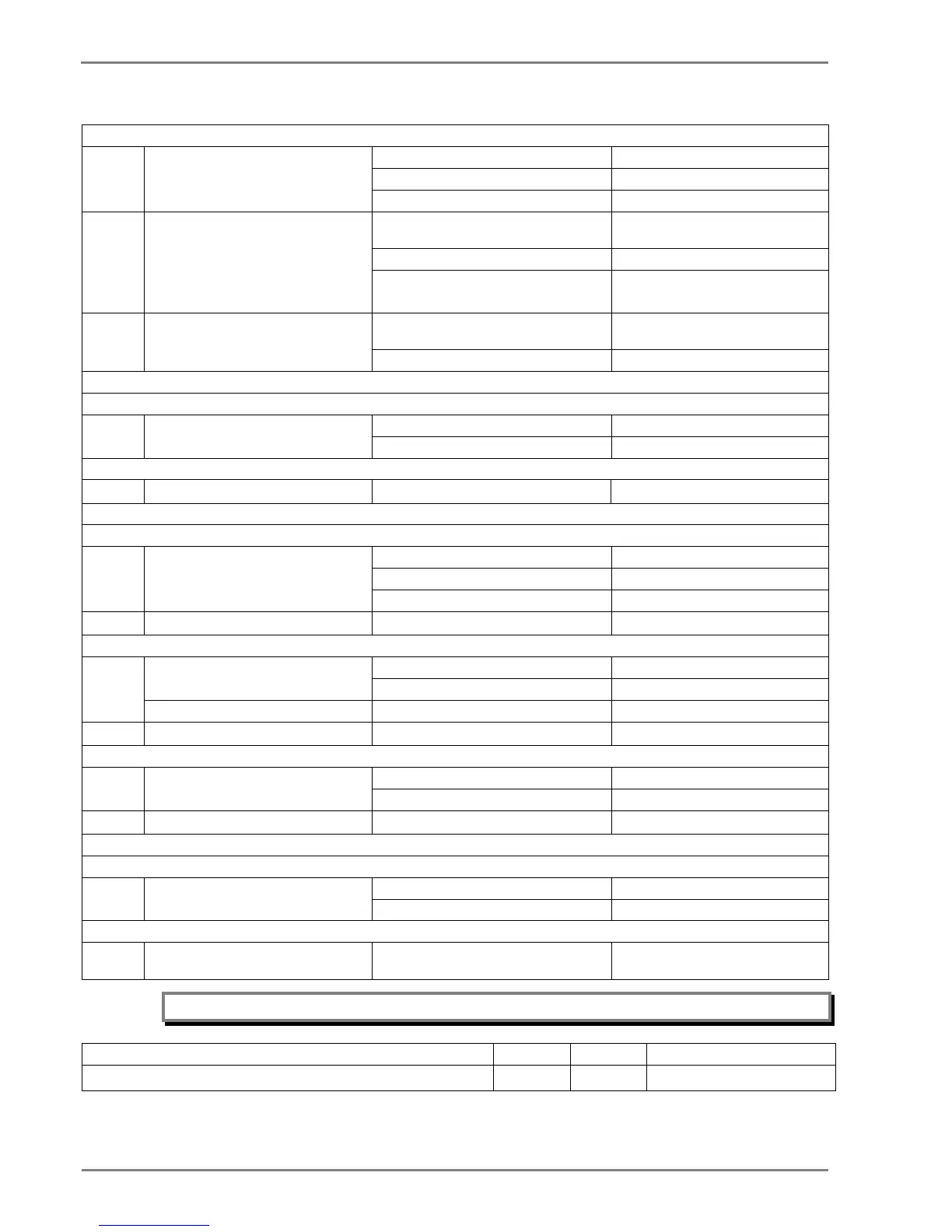
13 Technical Specifications
Negative Phase Sequence Overcurrent
I.
Operating value Pick-up Setting ±5%
Minimum trip level (IDMT)
II.
Operating time IDMT characteristic shape
As per clause 5.2 of 60255-
50 ms whichever is greater
± 5% or 55 ms whichever is greater**
** Reference condition Currents applied at 2x pick-up level or
higher
III.
Set delay ±7.5% or 55 ms whichever is
IDMT (only for IEEE & US curves)
2nd Harmonic
I.
Operating value 2ndHarm Thresh Setting ± 15%
I>lift 2H Setting ± 15%
Thermal alarm/trip/lockout Setting accuracy Setting ±5%
Operating time Calculated time ±7.5%
Reset value 97% of thermal setting ±5%
Cooling Time Accuracy ±15% of theoretical time
Operating time DT operation ± 5% or 55 ms whichever is greater
II.
T inhib DT operation ±5% or 55 ms whichever is greater
CB Fail
I.
Operating time DT operation ± 5% or 60 ms whichever is greater
CBF Reset <30 ms*
II.
Reset current (I< / IN1<)
*Note : Filtering time (typically 25ms) is added when CBF initiated by external binary input
I.
Prolonged start / Stall detection/
Stall Rotor Strt
Pick-up Setting ±5%
Timer accuracy ±5% or 55 ms whichever is greater
I.
Supervising Time / Time Betwe Start /
Inhib. Strt Time
Timer accuracy ±5% or 55 ms whichever is greater
Note: As per IEC60255-151 Class 5.2 (assigned error 5%) the tolerance calculated as below.
Value of characteristic quantity as multiple of setting value (Gs) 2-5 5-10 Above 10
Limiting error as multiple of an assigned error 2.5 1.5 1

 Loading...


