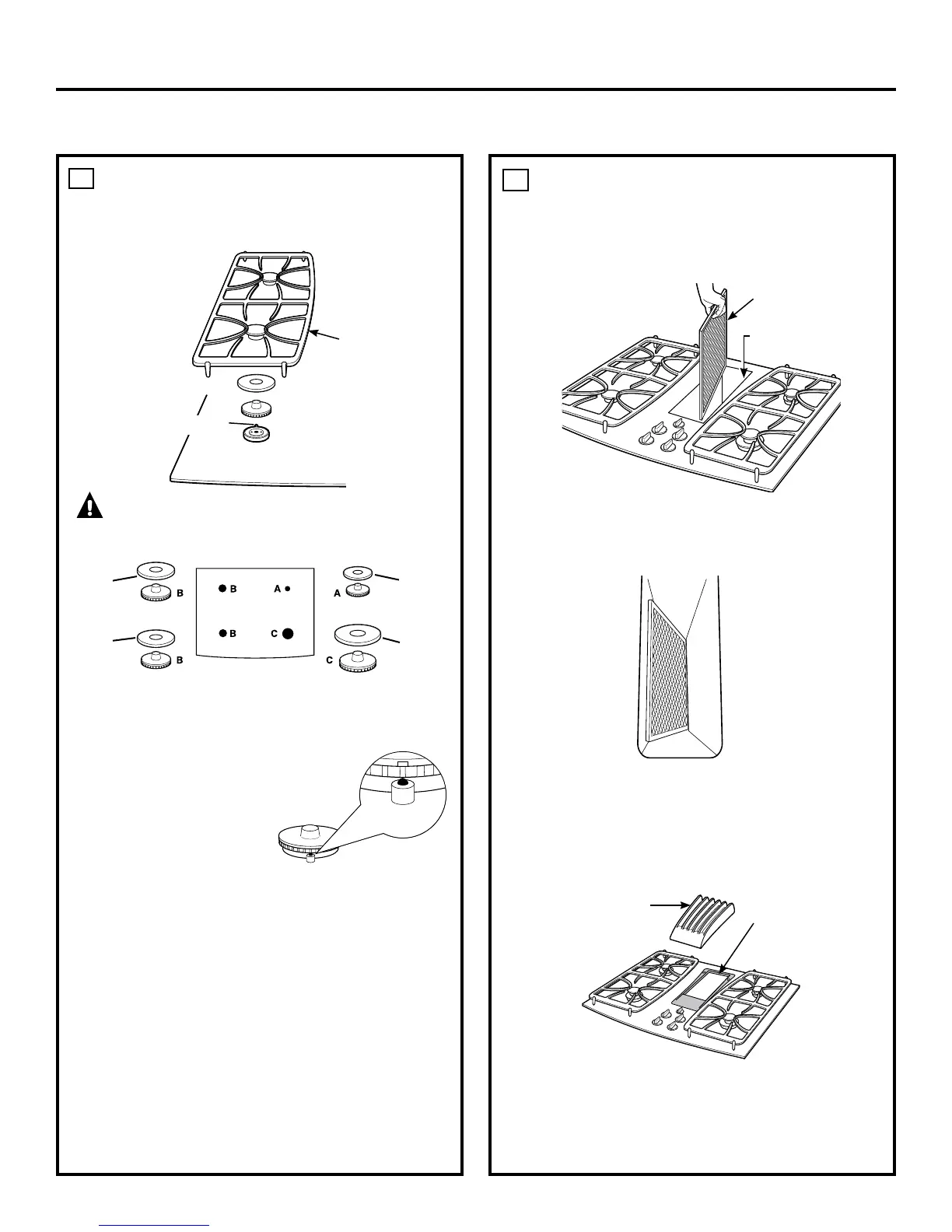
Assemble burner as shown
Do not operate the burner
without all burner parts in place
Place the burner heads on the burner bases matching the
letters Place the caps on the heads Make sure that the
heads and caps are placed
on the correct size burner The
burner heads and burner bases
are labeled A, B and C to aid
reassembly There is one small
(A), two medium (B) and one
large (C) head and cap
Make sure the notch in the
burner head is positioned toward the electrode Rotate the
burner head around the burner base until it is level and
securely seated
Place the grates over the burners
• Push in one control knob and turn to position
• The igniter will spark and the burner will light; the igniter
will cease sparking when the burner is lit
• First test may require some time, while air is flushed
out of the gas line
• Turn knob to
• Repeat the procedure for each burner
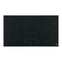
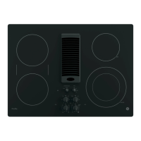
Do not operate the vent without the filter in place
• Place the filter diagonally through the vent opening
• Make sure it rests, at an angle, on the supports in the
vent opening
• Fit the vent grille gasket around the edge of the
downdraft vent opening Make sure the front of the
gasket is installed toward the front of the cooktop
• Carefully place the vent grille onto the gasket on the
downdraft opening
• Turn the vent fan speed control to , and
to make sure all speeds operate correctly
18
Vent Filter
Vent
Chamber
19
Grate
Burner head
Burner cap
Electrode
Burner base
Curved side
toward the
center
30
Grille
Vent Grille
Gasket
Medium
Head
and Cap
Medium
Head
and Cap
Front of Cooktop
Small
Head
and Cap
Large
Head
and Cap