– 38 –
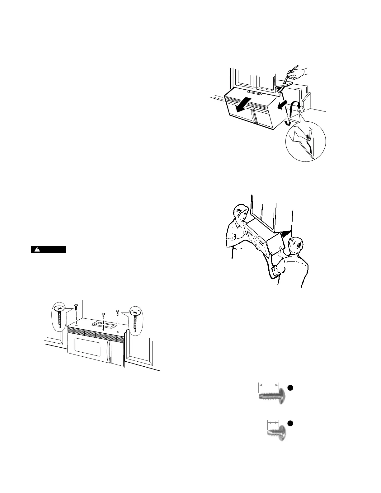
After swinging the top of the oven forward (away
from the cabinets) lift upward on the bottom of
the oven to release it from the mounting tabs of
the wall plate.
The oven can now be removed and lowered onto
a protective surface for further servicing.
OUTER CASE REMOVAL
Most of the screws you will be removing from
this point on, will be of two sizes (1/2” shank and
3/8” shank phillips
head screws). To help you in
reassembly, each of the accompanying illustra-
tions will contain an A or a B to help you identify
the proper screw location.
SERVICEABILITY - OVEN REMOVED FROM
WALL MOUNTING PLATE
The following components require the oven to be
removed from the wall mounting (removed from
installation) plate prior to replacement:
• Cavity T.C.O.
• Humidity sensor
• Vent motor
• Upper halogen lamps
• Upper halogen rear T.C.O.
• Upper halogen front T.C.O.
• Upper halogen blower
• Oven cavity thermistor
• Magnetron blower
• Magnetron tube
• Magnetron T.C.O.
• Lower halogen blower
• High voltage transformer
• Damper door assembly
• Thermal fuse
• Oven cavity lamp
• Vent motor
• Vent motor Capacitor
REMOVING OVEN FROM WALL PLATE
CAUTION
The oven is secured to the cabi-
nets with 3 mounting screws located at the top of
the oven (screws pull oven up tightly against top
cabinets. Once these three screws are removed
the oven will fall forward unless held in place as
shown in the illustration to the right.
With the mounting screws removed, swing the
top front of the oven forward while supporting the
bottom. Note in the illustration at the top right,
that the oven is hinged at the bottom. The oven
has slots in the bottom of the oven frame which
mount into tabs on the wall plate.