– 29 –
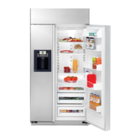
Dispenser Control Panel
The dispenser control panel contains the control
module and room ambient thermistor. The panel
is available in black or white. Stainless steel
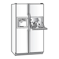
models come with black trim. To remove the
dispenser control panel on stainless steel front
models, insert a fl at-bladed screwdriver and lift
the frame outward to release the 15 retaining
hooks from the freezer door. Protect the freezer
door with cloth or tape to prevent marring the
surface.
To remove the dispenser frame on trimmed
models, remove the door handle fi rst, then slide
out the top panel. The dispenser cover can then
be removed by pulling it away from the door front.
Note: Some force is required to remove the trim
frame.
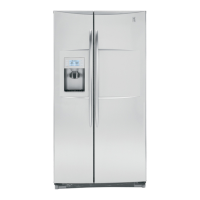
Stainless Steel Front
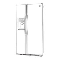
Trimmed Front
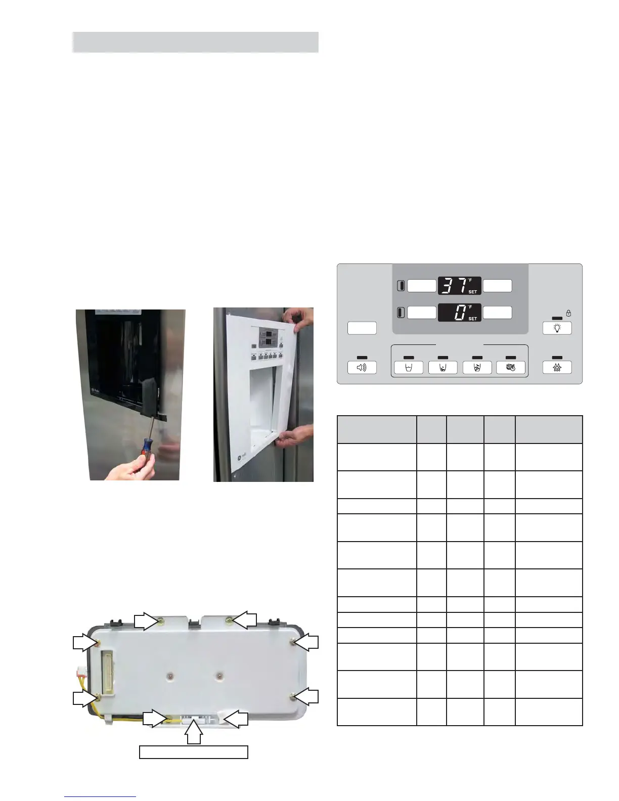
Ambient Thermistor
Control Module
• The control module is located on the back of
the dispenser control panel.
• The control module is held in place by 8
Phillips-head screws.
• The ambient thermistor is clipped to the
bottom of the module housing.
Testing the Dispenser Control Pads
Run the HMI Self-Test 0 6 (see
Service
Diagnostics). If any portion of the test fails, the
control module pads can be tested at the CN04
connector on the terminal block (see Terminal
Block Panel
).
Disconnect the CN04 connector and read the
resistance between the wires to the control
module. When each pad is pressed, a reading of
approximately 10K Ω should be present between
the pins as shown in the chart below.
As an example, when the
REFRIGERATOR COLDER
pad is pressed, 10K Ω should be present
between the purple and white/blue wires (pin #8
and pin #14).
Pad
Description
Pin Wire Pin Wire
REFRIGERATOR
COLDER
8 Purple 14 White/Blue
REFRIGERATOR
WARMER
9 Gray 14 White/Blue
FREEZER COLDER 10 White 14 White/Blue
FREEZER WARMER 11
Light
Blue
14 White/Blue
DISPLAY
TEMP
12
White/
Black
14 White/Blue
DOOR ALARM 13
White/
Red
14 White/Blue
WATER 8 Purple 15 White/Yellow
CRUSHED 9 Gray 15 White/Yellow
CUBE 10 White 15 White/Yellow
QUICK ICE 11
Light
Blue
15 White/Yellow
RESET FILTER 12
White/
Black
15 White/Yellow
LIGHT/LOCK 13
White/
Red
15 White/Yellow
ICE DISPENSER
HOLD 3 SECS
LIGHT
QUICK ICECUBEDCRUSHEDWATERDOOR ALARM
LOCK
RESET FILTER
HOLD FOR
3 SECS
TO A CTI VAT E
COLDER WARMER
DISPLAY
TEMP
COLDER WARMER
0º
F IS RECOMMENDED
ADJUST TEMPERATURE
37º F IS RECOMMENDED
REFRIGERATOR
FREEZER
 Loading...