– 32 –
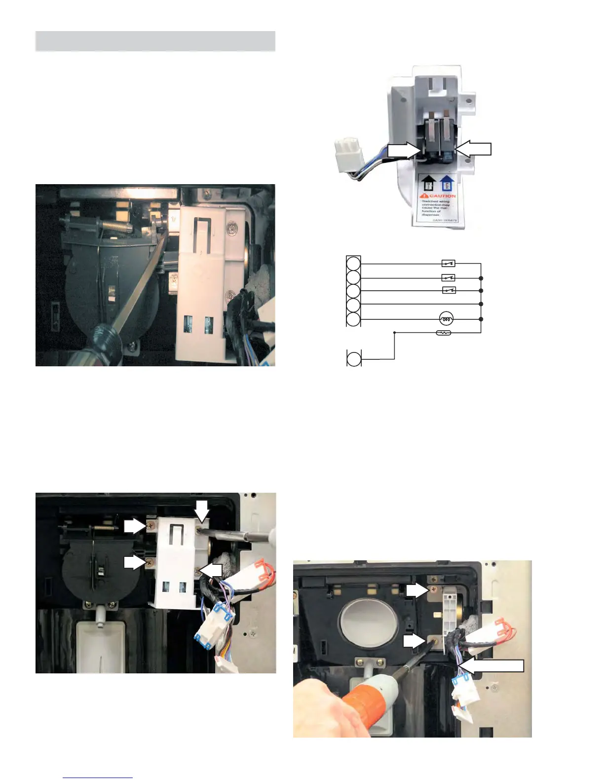
Duct Door Motor
The duct door motor rotates an eccentrically
shaped plastic cam which operates the duct door.
To remove the duct door motor:
1. Manually rotate the motor cam until the cam
lobe points forward.
2. Remove the 2 Phillips-head screws from the
motor mounting bracket. (Photo shown with
cam removed.)
Duct Motor
Tab
Tab
The duct door motor switches are held in place by
2 tabs.
Duct Door Motor Switch Housing
The dispenser motor operates through 2
switches located in a housing at the top, right
corner of the dispenser cavity. The dispenser
motor switch housing is held in place by 4
Phillips-head screws.
Duct Door Assembly
Duct Door
The dispenser control panel must be removed
before removing the duct door.
Insert a fl at-blade screwdriver between the duct
door (top right corner) and the switch housing.
Use the screwdriver to slide the door to the left,
until the hinge pin is free.
EXT - SENSOR
DISPENSER LAMP
ICE ROUTE SW 1
ICE ROUTE SW 2
DISPENSER SW
1
2
3
4
5
BLUE
PURPLE
WHITE
GRAY
LIGHT BLUE
RED
CN02
CN03
12
RED
 Loading...