– 41 –
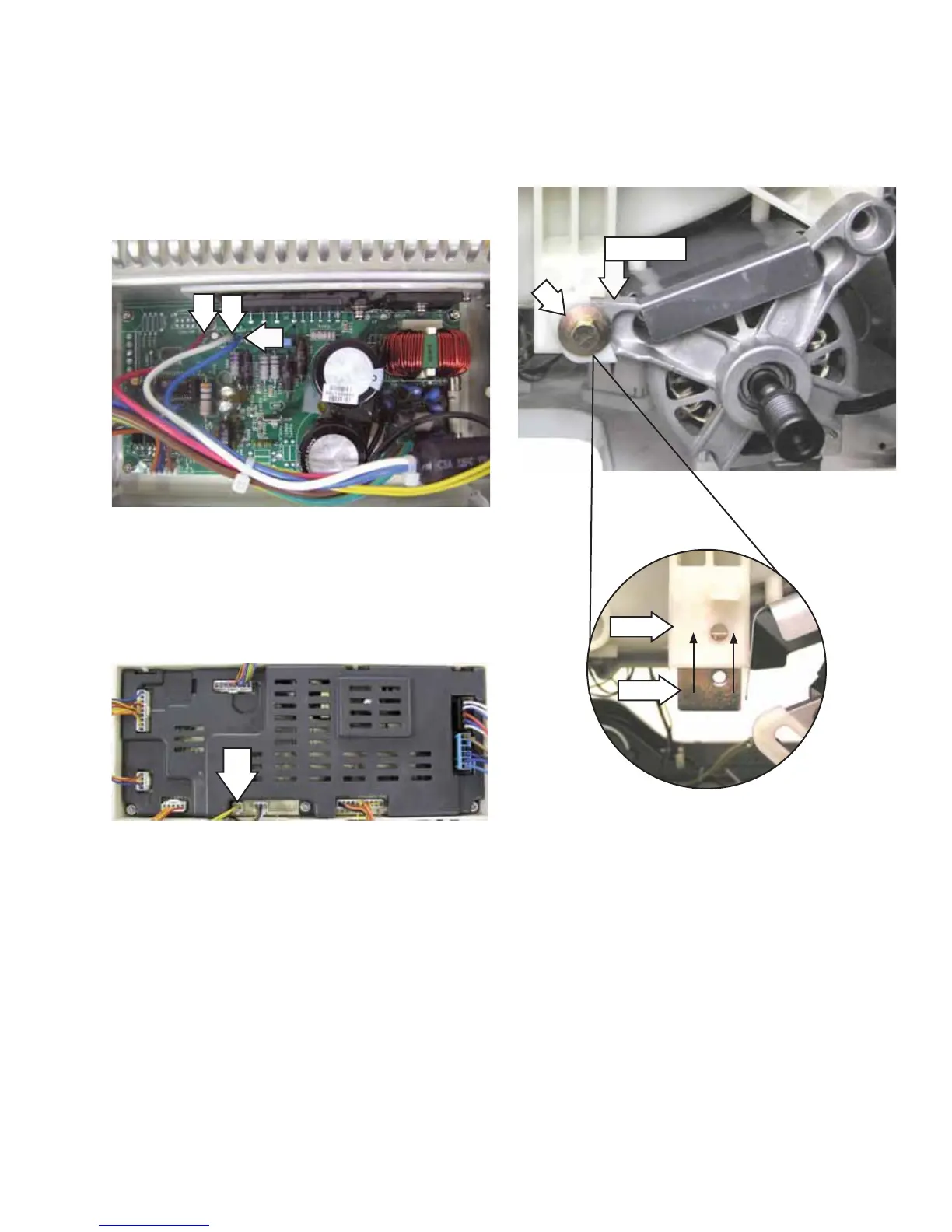
Note: The sensor and sensor wiring can be checked
at the power board assembly. Check for a resistance
value of approximately 118 Ω resistance between
the 2 yellow wires located on the wire harness
located at J79.
On the inverter board, check for an approximate 5.
resistance value of 6 ohms between any two of
the three terminals:
A to B (Blue to white) - 6 • Ω
A to C (Blue to red) - 6 • Ω
B to C (White to red) - 6 • Ω
B
C
A
J79
(Continued Next Page)
To remove the motor:
Remove the belt. (See 1.
Belt.)
Remove the 2.
1
/
2
-in. bolt from the threaded plate
that holds the motor arm to the outer tub.
Slot
Plate
Motor Arm
Note
The threaded plate can fall out of the recessed •
slot in the motor mount. Ensure this plate is
reinserted in the slot upon reassembly.
When reinstalling bolt, apply Locktite (Part # •
WX5X1005) to bolt threads. Ensure motor arm
is at lowest position under motor bolt before
tightening.
 Loading...