– 39 –
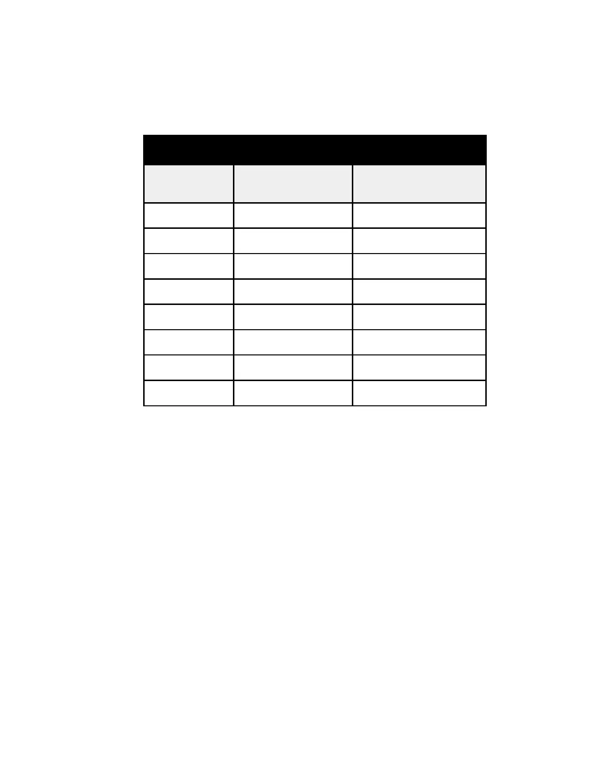
NOTE: The thermistor’s resistance has a negative coefficient. As the temperature increases, the
thermistor’s resistance decreases.
seulaVrotsimrehT
erutarepmeT
)C(seergeD
erutarepmeT
)F(seergeD
ecnatsiseR
smho-oliKni
03-22-k88 Ω
02-4-k4.84 Ω
01-41k6.72 Ω
023k3.61 Ω
0105k01 Ω
0286k2.6 Ω
0368k4 Ω
04401k6.2 Ω
Thermistors
This main control board uses input from 4 thermistors. These thermistors are located in the fresh food
section, the freezer section, and on the evaporator. The main control board monitors the thermistors to
determine the temperature in these areas of the unit and determines which components to run and
when to run them based on this information.
Thermistors can also be checked using diagnostic mode.
 Loading...