Installation Instructions
18
INSTALLATION—RECIRCULATING
DUCTWORK, WIRING LOCATIONS
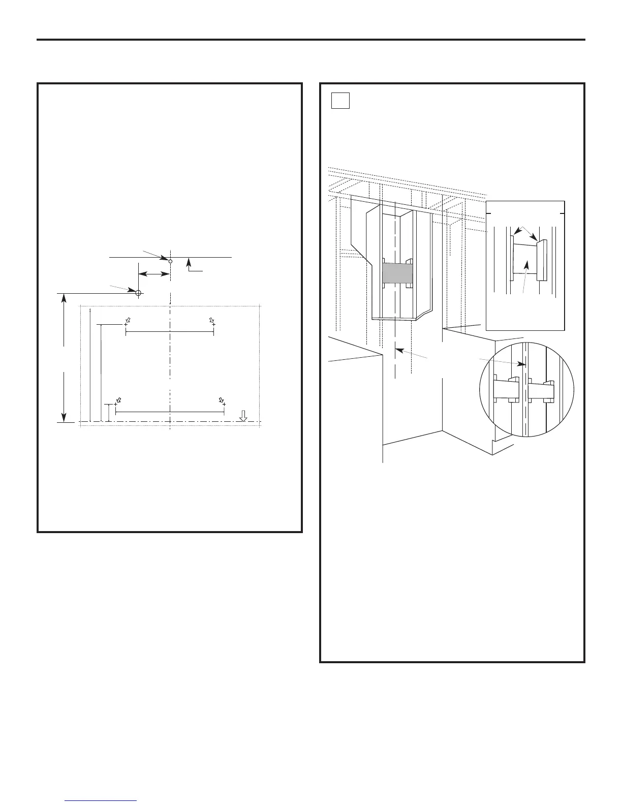
• Determine the exact location of the vent hood.
• Locate the template packed with the literature.
• Measure 36" from the floor to the top of the cooking
surface. Add hood installation height determined on
pages 8 and 13. Mark that location.
• Tape the template in position along the penciled line.
CHECK TO BE SURE THE TEMPLATE IS LEVEL.
• Use a level to draw a line straight up, from
the centerline on the template to the ceiling.
HOUSE WIRING LOCATION:
• The junction box is located on the top left side
of the hood.
• Wiring should enter the back wall at least 18"
above the bottom of the hood, and within 5"
of the centerline.
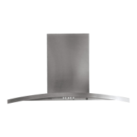
INSTALL FRAMING
FOR HOOD SUPPORT
IMPORTANT: Framing must be capable
of supporting 100 lbs.
If drywall is present, mark the screw hole locations
for the top mounting brackets. Remove the template.
• Cut away enough drywall to expose 2 vertical studs
at the bracket location indicated on the template.
• Install a horizontal support at least 1" x 12"
between two wall studs at the mounting screw
location. The horizontal support must be flush with
the room side of the studs. Use cleats behind both
sides of the support to secure to wall studs.
NOTE: 2 horizontal supports will be needed if there
is a stud located between the horizontal screw
locations (see figure).
IMPORTANT: Reinstall drywall for an even mounting
surface.
1