Operation
30
SecoVac 3.3kV-27kV Embedded Pole Vacuum Circuit Breaker
S9
512221
44
S5
22
S5
43
21
13
14
11
1250 4914 48
58 56
81
82
S5
14
13
S5
14
S8 S8
34
24
S8
13 33
23
S8
54
53
24
34
33
23
S9
54
53
S9
S9
2 474 57 55
36 34
35
20
(21)
(13)
(21)
S3
(14)
S3
(22)
S1
(22)
(52)
(51)
V1
2426
25
V2
Spring Charge Motor Closing Circuit
10
53 54 31 32
S8
44
43
44
S9
43
371513 1917 33 3938
S4
S5
(74)
S5
(54)
(2)
(5)
(3)
K0
(53)
S5
(73)
(12)
(11)
S5
(13)
(14)
S2
CC
K0
TC
64
72 624232
4131
63
71 61
8424 34
8323 33
S5
V4
V3
Breaker Interlock Circuit
52
Opening Circuit
30
2735 9723 2928
92
91
94
93
16
6
18
8
40
Truck Interlock Circuit
1
M
BC
A~
D~
2
1
C+ B-
ZC
V5
Y4
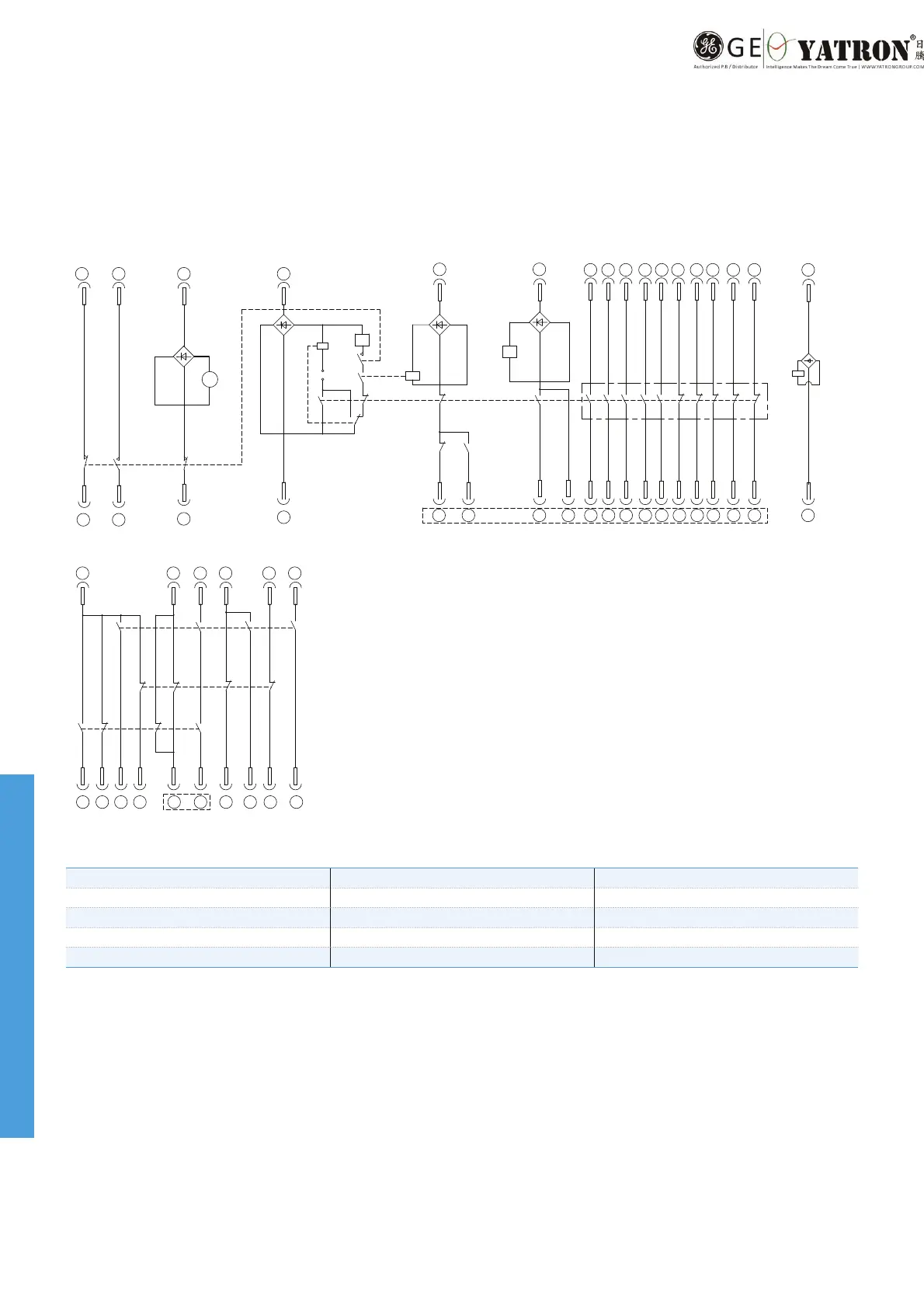
Internal Wiring Diagram
S9: Limit switch (service position) CC: Closing coil KO: Anti-pumping relay (optional)
S8: Limit switch (test position) TC: Trip coil BC: Electromagnet for locking (optional)
S4: Electromagnet for locking's auxiliary switch M: Spring Charge Motor ZC: Electromagnet for locking truck (optional)
S: Auxiliary switch V1~V4: Rectier
S1~S3: Energy storing limit switch
Note:
1. This wiring diagram describes that a b
re
aker is open, racked to test position with spring in discharge state.
2. The polarity in dashed frame should be connected to common DC voltage terminal.
Withdrawable Type
 Loading...