Operation
32
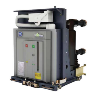
SecoVac 3.3kV-27kV Embedded Pole Vacuum Circuit Breaker
Fixed Type
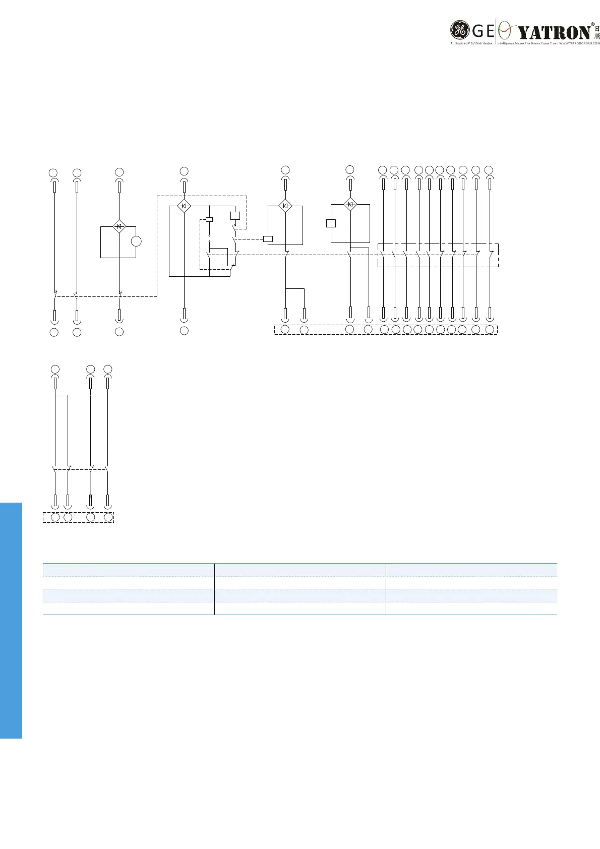
Spring Charge Motor Closing Circuit Breaker Interlock Circuit Opening Circuit
36 34
35
20
(21)
(13)
(21)
S3
(14)
S3
(22)
S1
(22)
(52)
(51)
V1
25
26
24
V2
10
50
31 32
S4
S5
(74)
S5
(54)
(2)
(5)
(3)
K0
(53)
S5
(73)
(12)
(11)
S5
(13)
(14)
S2
CC
K0
TC
V4
V3
52
30
51
371513 1917 33 3938
64
72 624232
4131
63
71 61
8424 34
8323 33
S5
2735 9723 2928
16
92
91
6
18
8
94
93
2221
44
S5
22
S5
43
21
11
12
14
81
82
S5
14
13
S5
2 4
M
BC
S4: Electromagnet for locking's auxiliary switch CC: Closing coil KO: Anti-pumping relay (optional)
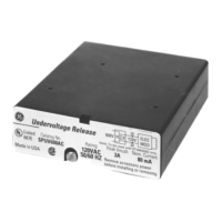
S: Auxiliary switch TC: Trip coil BC: Over current release coil (optional)
S1~S3: Energy storing travel switch M: Energy storing motor ZC: Electromagnet for locking (optional)
V1~V4: Rectier C: Control
Note:
1. This wiring diagram describes that a breaker is uncharged and is in an open state.
2. The polarity
in dashed frame should be consistent when the operation vo
ltage is DC.
Internal Wiring Diagram
 Loading...