Maintenance
Electrical contact den simeter threshold inspection
GE Information08- 2016 L51- 108EN/06
3/8
Linking the densimeter on the control tool
Process
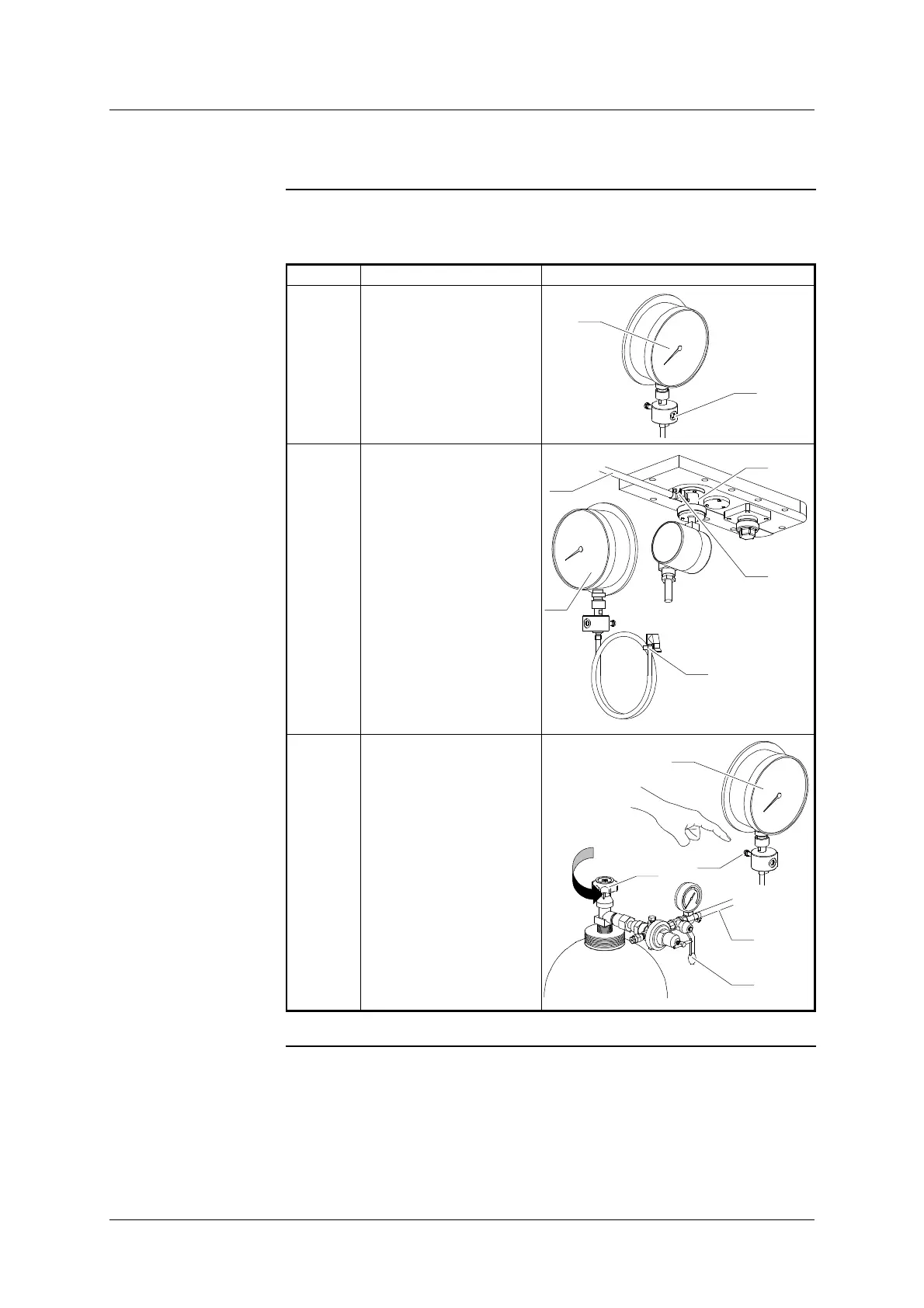
The table below gives the process to link the densimeter on the control
tool:
Step Action Diagram
1 Check that the
“REGULATION” screw
(20) - of the gauge (11) -
is in “valve closed” posi-
tion (screwed).
11
20
2 Connect the pipe (12) of
the gauge (11) on the
valve (24) of the connec-
tion valve block (5).
5
24
11
12
12
3 Briefly open the SF
6
gas
bottle tap (21) and the
cock (22) of the pressure
reducer to eliminate any
air inside the pipe (23)
(approx.
20 s at low
flow- rate).
Connect the pipe (23) on
the valve (10) of the
gauge (11).
SF
6
21
22
23
10
11
 Loading...