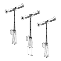
Installation
Coupling of column and chambers
GE Information L31- 7138EN/02
7/16
11- 2016
Final coupling, continued
Removing the
chamber transport
cover
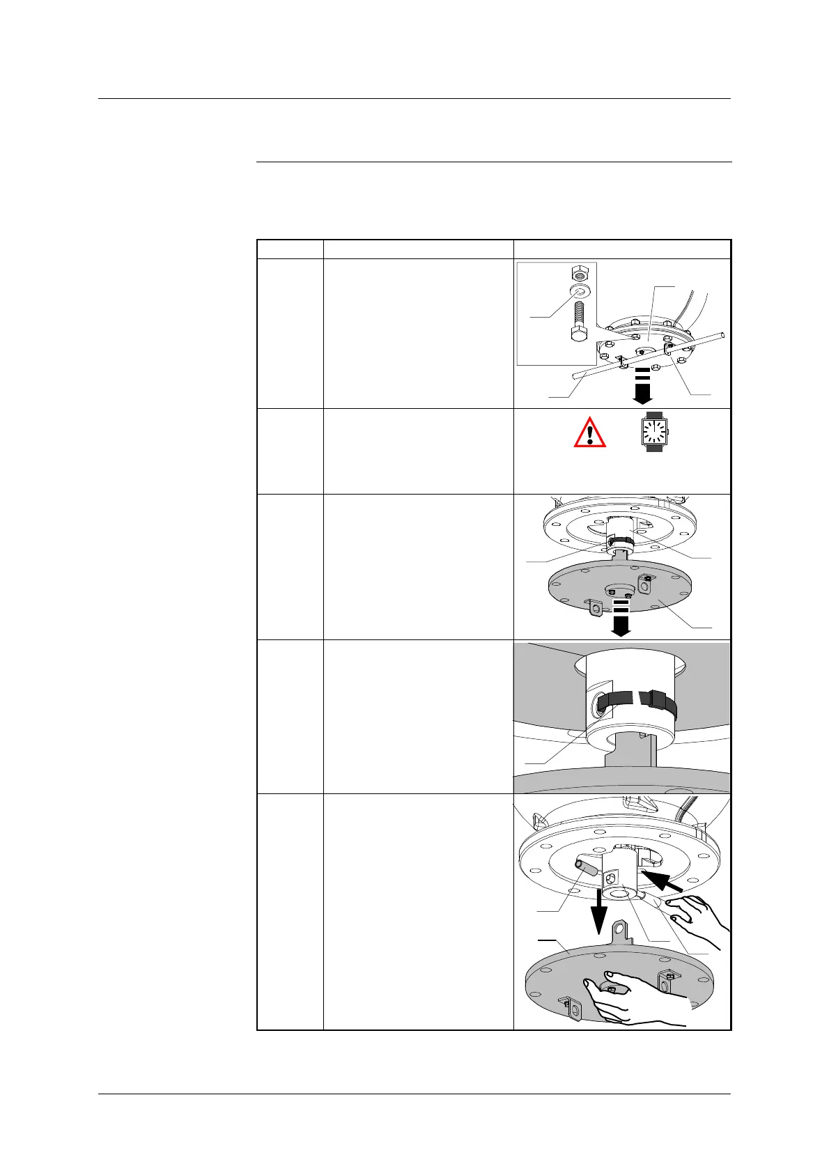
The table below shows the steps for removing the chamber transport cover:
Step Action Illustration
1 Remove the fixings (40) and
insert the lever (32) through
the bracket rings (7).
Pull on the lever (32) to open
the cover (4).
Hold on two two of the cover
bolts (40) for later use.
32
x8
HM16-55
40
7
4
2 Start timing.
(The final chamber/column
coupling operations should
becompletedinatimeof
40 min).
3 Pull off the cover (4) to free
the stop ring (8) and ’Rilsan’
collar (9).
9
8
4
4 Using wire cutters, cut
through the ’Rilsan’ collar (9)
holding the connector tube
and remove it.
9
5 Using the coupling tool (35),
remove the tube (10) and sep-
arate the cover (4) from the
stop ring (8).
8
10
35
4
Continued on next page.
 Loading...