Installation
Coupling of column and chambers
GE Information L31- 7137EN/02
10/18
11- 2016
Final coupling, continued
Removing the
chamber transport
cover
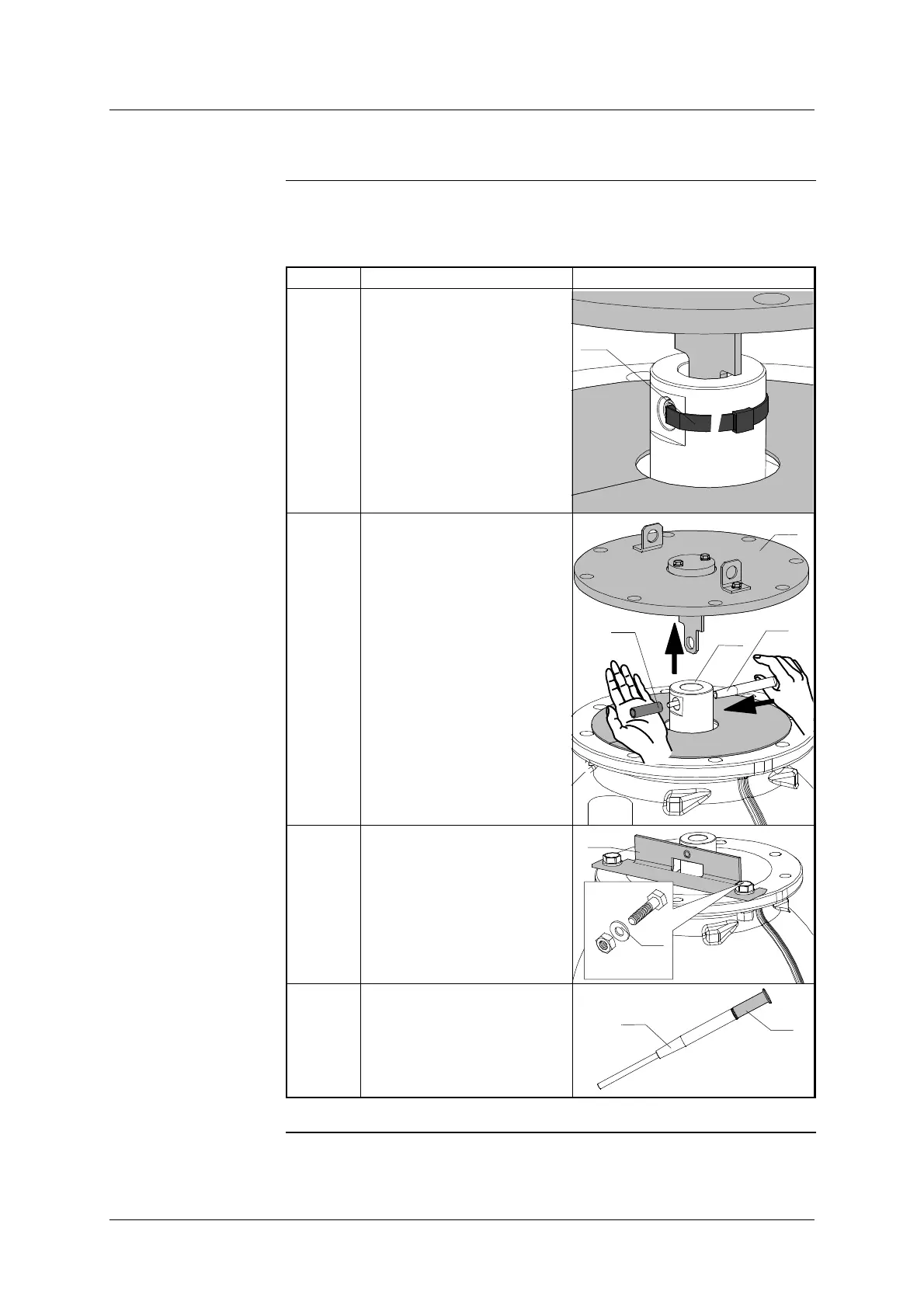
The table below shows the steps for removing the chamber transport cover:
Step Action Illustration
5 Using wire cutters, cut
through the ’Rilsan’ collar (9)
holding the connector tube
and remove it.
9
6 Using the coupling tool (35),
remove the tube (10) and sep-
arate the cover (4) from the
stop ring (8).
10
35
4
8
7 Fit the trolley stop (34) and fix
in place using the bolts (40)
recovered from the transport
cover, hand tightening them.
x2
HM16-55
34
40
8 Prepare the fitting tool (35)
by screwing the coupling pin
(24) onto its end, hand tight-
ening.
35
24
Continued on next page.