Installation
Coupling of column and chambers
GE Information L31- 7137EN/02
16/18
11- 2016
Final coupling, continued
Connection
chambers/column
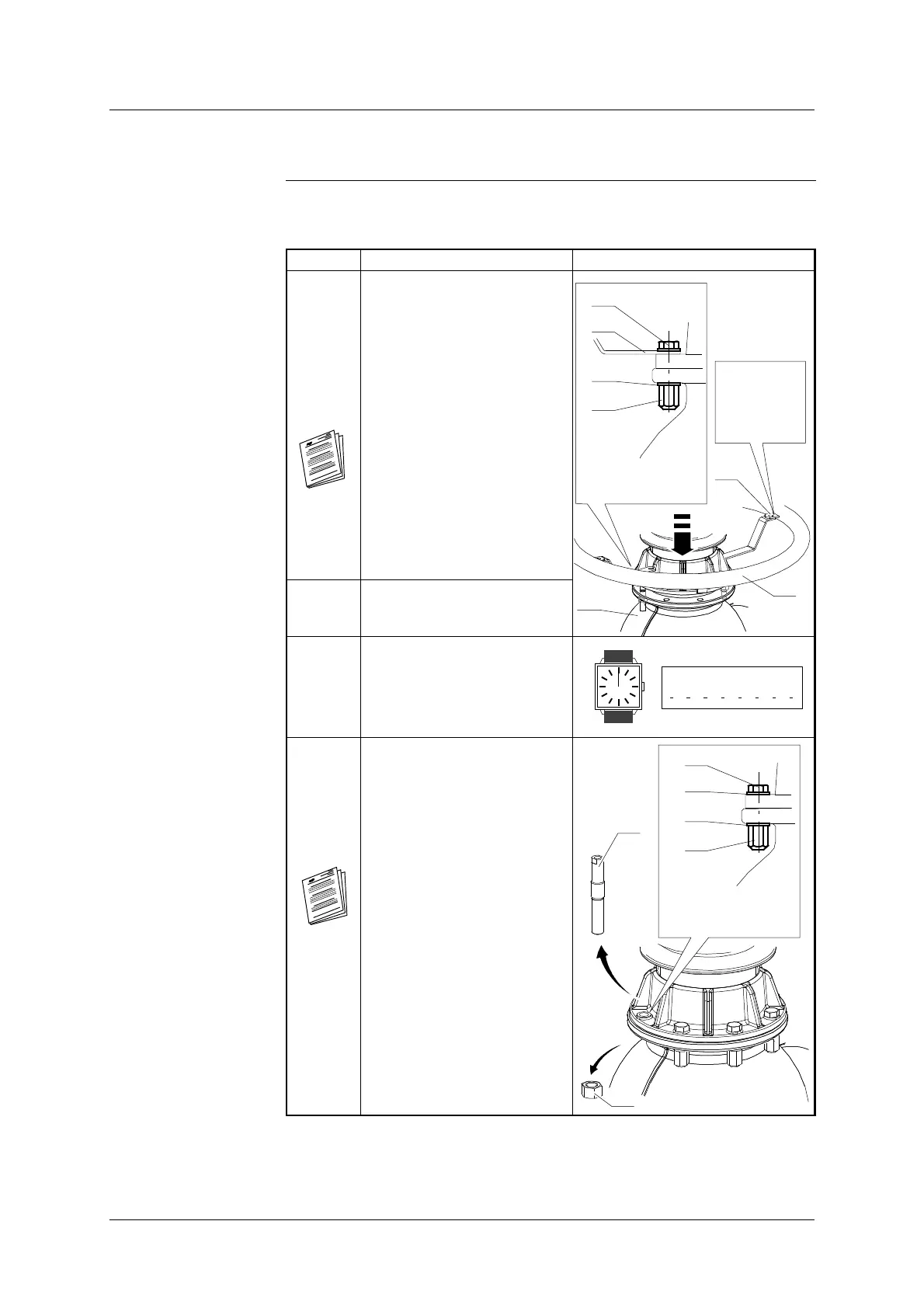
The table below shows the steps for connecting the chambers to the column:
Step Action Illustration
4 Slowly lower the column onto
the breaking chamber casing
(2).
Position the lugs (51) for the
corona shield (50) on the rim
of the column then attach
using bolts (21), washers (22)
and special nuts (23) - See
’Locking Fixings’.
See module ’General
assembly procedures’.
Lock the nuts (23) at the
appropriate torque, immobil-
ising the bolt heads (21).
H M16- 65 (75)
13,5 daN.m
x6
21
22
23
51
x4
HM10-30
3,2 daN.m
2
52
50
5 T ighten all fixings (52) to their
appropriate torque level.
6 End of coupling operation -
stop the timer and note the
time taken.
7 Remove the last section (A)
and the nut (41) from the cent-
ring pins.
Fix the last bolts (21), wash-
ers (22) and special nuts (23)
referring to ”Locking fix-
ings”.
See module ’General
assembly procedures’.
Lock the nuts (23) at the
appropriate torque, immobil-
ising the bolt heads (21).
H M16-65/75
13,5 daN.m
x2
(A)
41
21
22
23
22
Continued on next page.