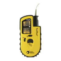
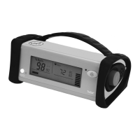
TruSat Technical Reference Manual
4–12
4.6 Repair procedures
WARNING: Power OFF and disconnect the monitor from external power
before performing any procedure that involves disassembly of the monitor.
WARNING: Internal electronic components are susceptible to damage by
electrostatic discharge. To avoid damage when disassembling the monitor,
observe the standard precautions and procedures for handling static-
sensitive components.
Tools:
• Phillips screwdriver, #1
• Small, flat-blade screwdriver
• Nut drivers, 3/8 inch (for line power jack) and 7/16 inch (for ComWheel encoder)
Monitor disassembly
Disassemble the parts on the right side, the left side, and within the housing only as
needed to access the part or parts to be replaced. Then go to the assembly instructions
to complete the procedure.
Refer to the assembly drawing as you disassemble the monitor. See TruSat assembly
drawing later in this manual.
Right (ComWheel) side disassembly
Parts:
Right bumper Speaker
Right inner end plate ComWheel knob
ComWheel encoder
(with spacer, washer, and nut)
Outer end plate
1. Power OFF and disconnect the power cord and other cables from the monitor.
2. Remove the 3 screws that secure the right bumper assembly to the housing.
3. Note the orientation of the ComWheel encoder cable and the speaker cable. Each is
“keyed” for correct connection to the System board. Carefully disconnect both cables
from the System board.
4. Using a small, flat-blade screwdriver, gently pry the edges of the ComWheel knob
away from the bumper. Grasp the ComWheel and pull it off the encoder post.
5. Lift the right inner end plate out of the bumper. Using a 7/16 inch nut driver, remove
the nut and washer that secure the ComWheel encoder to the end plate. Slide the
encoder and spacer out the other side of the end plate.
6. Lift the speaker out of the bumper.
Left side disassembly
Parts:
Left bumper Left inner end plate
SpO
2
code ring Outer end plate
1. Remove the 3 screws that secure the left bumper assembly to the housing.
2. Lift the left inner end plate out of the bumper and remove the SpO
2
code ring from
the bumper.
 Loading...