5-6 L60 Line Phase Comparison System GE Multilin
5.1 OVERVIEW 5 SETTINGS
5
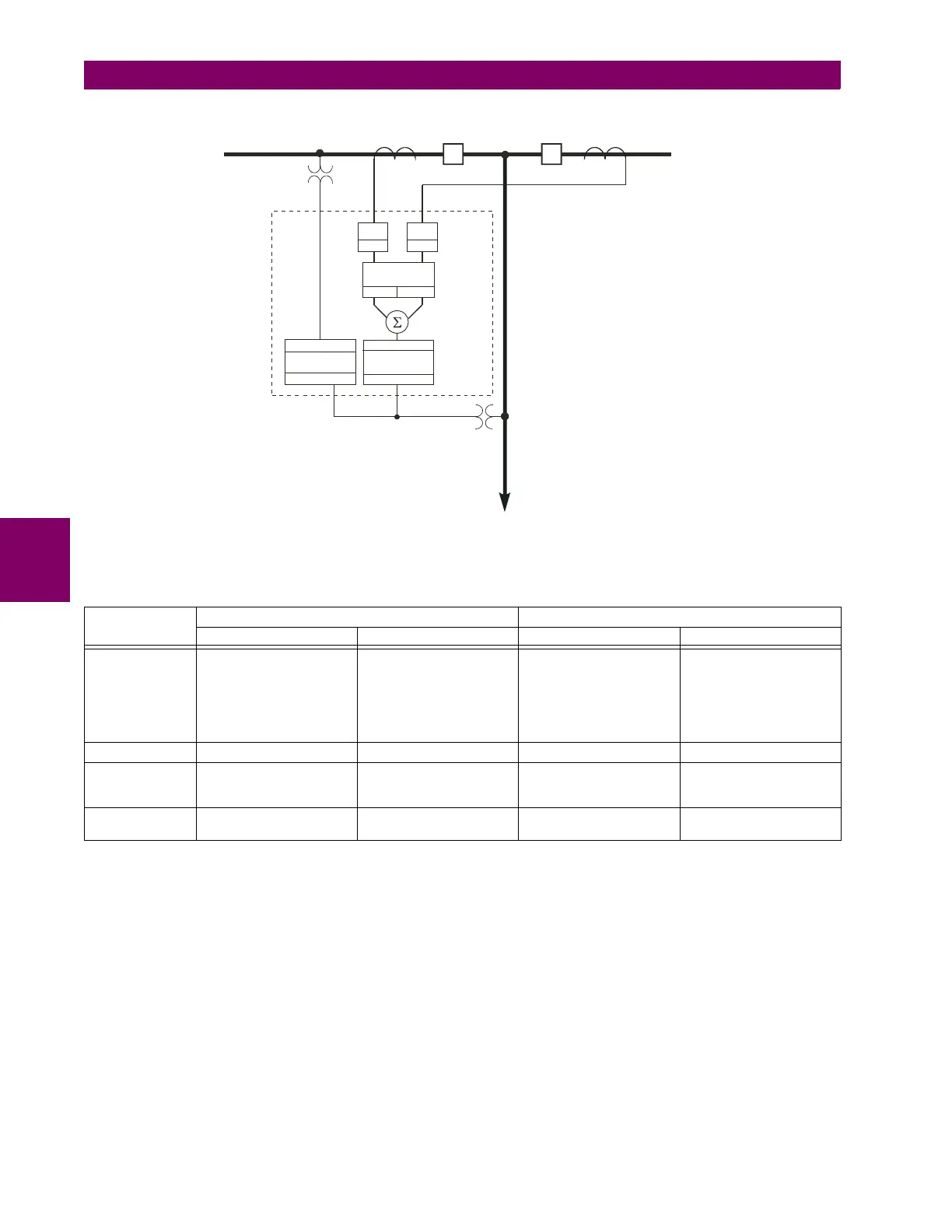
Figure 5–1: BREAKER-AND-A-HALF SCHEME
The following table explains how to configure the sources for full functionality.
Table 5–1: SOURCE CONFIGURATION FOR PHASE COMPARISON
FUNCTION CT/VT MODULE 1 (TYPE 8P) CT/VT MODULE 1 (TYPE 8F)
SRC 1 SRC 2 SRC 3 SRC 4
Phase current F1 to F3 CT channels
(used for 87PC first current
and Breaker Failure 1)
Not available L1 to L3 CT channels
(used for 87PC second
current and Breaker
Failure 2). This source is
configurable only if a
second CT/VT module is
ordered.
Sum of F1:F3 and L1:L3
(used for distance and
overcurrent)
Ground current F1 (Ground overcurrent) Not available --- ---
Phase voltage Not available Not available --- Three-phase line VT for
distance and
synchrocheck
Auxiliary voltage Not available Not available Single-phase bus VT for
synchrocheck
---
831786A1.CDR
Protected
line
VT2
CT2
CB2CB1
CT1
VT1
1PH
L60
Phase
comparison
SRC 1 SRC 2
SRC 3
Distance and
overcurrent
SRC 3
3PH
Synchrocheck 1
SRC 3
SRC 1
SRC 1 SRC 2
BF 1 BF 2

 Loading...


