GE Multilin L60 Line Phase Comparison System 9-3
9 APPLICATION OF SETTINGS 9.1 PHASE COMPARISON ELEMENT 87PC
9
87PC TRANS BLOCK RESET:
This setting is used to reset transient blocking and allow tripping. According to local conditions, setting should be consid-
ered as the sum of protection operating time and breaker opening time of the adjacent line and minus the Transient Pickup
value to override uncertainty during clearing external faults. The faster the fault clearing at the adjacent line, the lower set-
ting could be applied.
Ttr_rst = Tprot_adj + Tbreak_adj – Ttr_pkp
where: Tprot_adj is the expected time of main protection operation on the adjacent line,
Tbreak_adj is the operation time of the breaker on the adjacent line,
Ttr_pkp is selected Transient Pickup time.
87PC BLOCK:
The user can define some cases when blocking of the phase comparison scheme is required. This setting will block the trip-
ping function. PLC alarm contacts indicating channel failure are usually assigned for this setting,. especially in blocking
schemes.
87PC CHNL LOSS TRIP WINDOW:
This setting is applicable to the 2TL-BL-DPC-2FL scheme only. The typical setting is 150 ms.
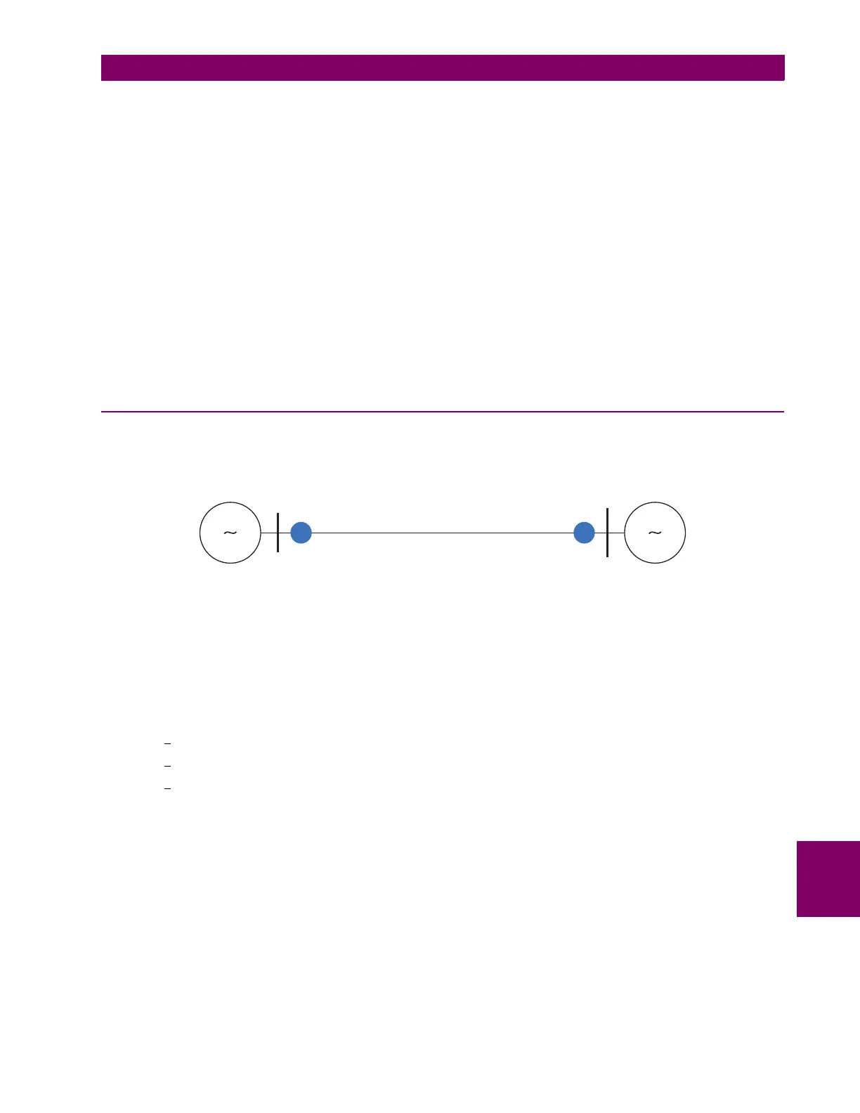
9.1.3 SETTINGS EXAMPLE
Consider settings for a single-circuit 765 kV line, 100 miles length, 50 ohms primary impedance, 5520 ohms shunt capaci-
tance of the line, maximum expected load of 2000 A, CT ratio 2000/5, minimum expected internal three-phase fault is
8000 A.
Figure 9–1: SETTINGS EXAMPLE
1. Mixed signal factor K =0.2
2. FDL pickup: I
FDL
= 1.1 × 2000 × 0.2 = 440 A or 440 / 400 = 1.1 A secondary.
The setting is 1.1 / 5 = 0.22 pu.
3. FDH pickup: I
FDH
= 4/3 × I
FDL
+ 0.375 × I
capac
= 1.33 × 440 + 0.375 × 80 = 615.2 A or 615.2 / 400 = 1.54 A secondary;
setting is 1.76 / 5 = 0.31 pu. Where I
capac
= 765000/(√3 × 5520) = 80 A
4. Stability angle:
φ
load = 2 × arcsin((2000 × 50 × √3) / (2 × 765000)) = 13.0°
φcapac = arctan(I
capac
/ I
FDH
) = arctan(80 / 615.2) = 7.4°
φ
s(deg) = 13.0°+7.4°+10° = 30.4°
Minimum recommended setting 60° (set as default) should be applied.
5. Check against requirement for trip supervision by distance relay: As minimum internal three-phase fault is much than
twice the maximum line load current, no distance element is required for be assigned to
FD INPUT setting.
2000/5
L60-1 L60-2
765 kV
2000/5
100 miles
831813A1.CDR
 Loading...


