3-28 L60 Line Phase Comparison System GE Multilin
3.2 WIRING 3 HARDWARE
3
3.2.10 L60 CHANNEL COMMUNICATIONS
As described earlier in this chapter, L60 communications channels reside on the special CT/VT module (type 8P). This
module allows for all possible 87PC scheme combinations (such as dual phase comparison or single-phase comparison,
two-terminal or three-terminal applications) in one module. The customer can upgrade or change the scheme at any time.
The L60 channel interface requires an external battery to drive inputs and outputs. The module can be used with any bat-
tery voltage. However, the battery voltage must be reflected in the
GROUPED ELEMENTS ÖØ SETTING GROUP 1(6) Ö PHASE
COMPARISON ELEMENTS Ö 87PC SCHEME ÖØ 87PC CH1(2) RX VOLT settings, which define the acceptable voltage threshold
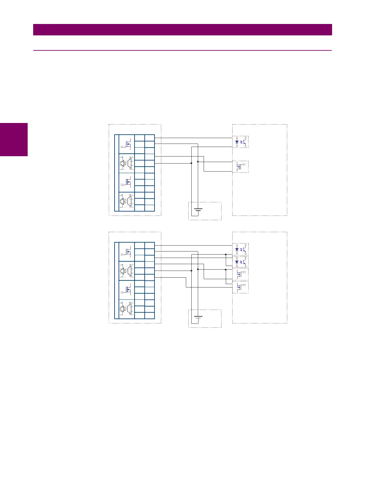
received from the PLC. The L60 communications outputs are MOSFETs and inputs are implemented with optocouplers,
excluding any galvanic connection between PLC connections and the relay boards.
Figure 3–28: L60 TO PLC CONNECTIONS FOR A TWO-TERMINAL LINE
The communications circuitry has the following characteristics for the transmitter and receiver.
Transmitter characteristics:
• Operating voltage range: 0 to 300 V DC (typical points: 15 V, 48 V, 125 V, 250 V).
• Output current limitation: 100 mA (maximum), 30 mA (nominal).
Receiver characteristics:
• Input voltage range: 0 to 300 V DC.
• Input impedance: 25 kohms.
• Input current: 10 mA at 250 V, 5 mA at 125 V, 2 mA at 48 V.
831784A1.CDR
COMMS INTERFACE INPUTS/OUTPUTS
~
~
~
~
~
~
~
~
~
~
~
~
BATT+
Tx1P
Tx1N
Tx Positive Ch 1
BATT-
Rx1P
Rx1N
BATT+
Tx2P
Tx2N
BATT-
Rx2P
Rx2N
L60
STATION
BATTERY
PLC
Rx Positive Ch 1
Tx Negative Ch 1
Rx Negative Ch 1
Common (+) Ch 1
Common (-) Ch 1
COMMS INTERFACE INPUTS/OUTPUTS
~
~
~
~
~
~
~
~
~
~
~
~
5a
5b
5c
6a
6b
6c
7a
8a
7b
8b
7c
8c
BATT+
Tx1P
Tx1N
Tx Positive Ch 1
BATT-
Rx1P
Rx1N
BATT+
Tx2P
Tx2N
BATT-
Rx2P
Rx2N
L60
STATION
BATTERY
PLC
Rx Positive Ch 1
L60 Comms 1
Single-phase
Comparison
5a
5b
5c
6a
6b
6c
7a
8a
7b
8b
7c
8c
L60 Comms 2
Dual-phase
Comparison

 Loading...


