5-96 L60 Line Phase Comparison System GE Multilin
5.4 FLEXLOGIC™ 5 SETTINGS
5
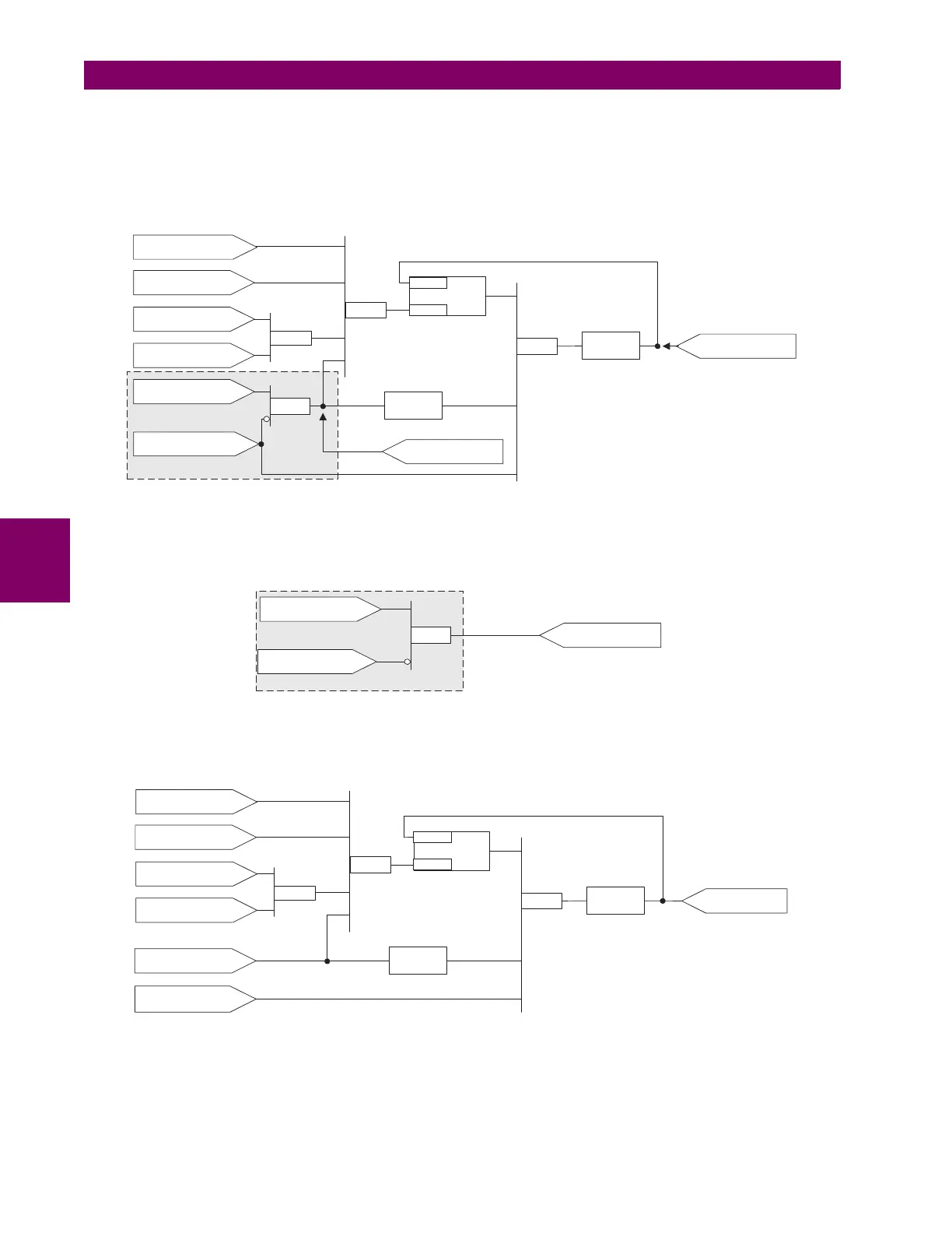
For the example shown above, the output of the AND gate is used as an input to both OR#1 and Timer 1, and must
therefore be made a virtual output and assigned the next available number (i.e. Virtual Output 3). The final output must
also be assigned to a virtual output as virtual output 4, which will be programmed in the contact output section to oper-
ate relay H1 (that is, contact output H1).
Therefore, the required logic can be implemented with two FlexLogic™ equations with outputs of virtual output 3 and
virtual output 4 as shown below.
Figure 5–35: LOGIC EXAMPLE WITH VIRTUAL OUTPUTS
2. Prepare a logic diagram for the equation to produce virtual output 3, as this output will be used as an operand in the
virtual output 4 equation (create the equation for every output that will be used as an operand first, so that when these
operands are required they will already have been evaluated and assigned to a specific virtual output). The logic for
virtual output 3 is shown below with the final output assigned.
Figure 5–36: LOGIC FOR VIRTUAL OUTPUT 3
3. Prepare a logic diagram for virtual output 4, replacing the logic ahead of virtual output 3 with a symbol identified as vir-
tual output 3, as shown below.
Figure 5–37: LOGIC FOR VIRTUAL OUTPUT 4
4. Program the FlexLogic™ equation for virtual output 3 by translating the logic into available FlexLogic™ parameters.
The equation is formed one parameter at a time until the required logic is complete. It is generally easier to start at the
output end of the equation and work back towards the input, as shown in the following steps. It is also recommended to
list operator inputs from bottom to top. For demonstration, the final output will be arbitrarily identified as parameter 99,
LATCH
CONTACT INPUT H1c
State=Closed
XOR
AND
Reset
Set
VIRTUAL OUTPUT 2
State=ON
VIRTUAL INPUT 1
State=ON
DIGITAL ELEMENT 1
State=Pickup
DIGITAL ELEMENT 2
State=Operated
OR #2 VIRTUAL OUTPUT 4
OR #1
(800 ms)
Timer 1
Time Delay
on Pickup
(200 ms)
Timer 2
Time Delay
on Dropout
VIRTUAL OUTPUT 1
State=ON
827026A2.VSD
VIRTUAL OUTPUT 3
CONTACT INPUT H1c
State=Closed
AND(2)
DIGITAL ELEMENT 2
State=Operated
VIRTUAL OUTPUT 3
827027A2.VSD
LATCH
CONTACT INPUT H1c
State=Closed
XOR
Reset
Set
VIRTUAL OUTPUT 2
State=ON
VIRTUAL INPUT 1
State=ON
DIGITAL ELEMENT 1
State=Pickup
OR #2
VIRTUAL
OUTPUT 4
OR #1
(800 ms)
Timer 1
Time Delay
on Pickup
(200 ms)
Timer 2
Time Delay
on Dropout
VIRTUAL OUTPUT 3
State=ON
VIRTUAL OUTPUT 1
State=ON
827028A2.VSD

 Loading...


