5-120 L60 Line Phase Comparison System GE Multilin
5.5 GROUPED ELEMENTS 5 SETTINGS
5
The negative-sequence overcurrent advanced fault detector element responds to the increment of the magnitude of the
negative-sequence current over a specified threshold. Thresholds are provided for low-set control of keying and high-set
operation control of tripping.
The following settings are available.
• NEG SEQ I_2 FD FUNCTION: This setting enables or disables the negative-sequence overcurrent fault detection.
Note that all fault detectors operate in parallel with the 87PC function. To effectively disable the overcurrent fault detec-
tors under the main 87PC menu, set their threshold very high.
• NEG SEQ I_2 FDL PICKUP: This setting specifies the pickup of the low-set stage of the element used to control the
key operation. The nominal current of the phase CT bank of the relay is 1 pu.
• NEG SEQ I_2 FDH PICKUP: This setting specifies the pickup of the high-set stage of the element used to control the
trip operation. The nominal current of the phase CT bank of the relay is 1 pu.
• NEG SEQ I_2 BLK: The fault detector is hard-wired to the 87PC scheme. It can be disabled permanently using the
function setting or blocked temporarily with this setting. This setting selects a FlexLogic™ operand that blocks this fault
detector when asserted.
• NEG SEQ I_2 FD TARGET: This setting controls targets of the negative-sequence overcurrent advanced fault detector
function. These targets operate independently from the 87PC targets.
• NEG SEQ I_2 FD EVENTS: This setting controls event recording of the negative-sequence overcurrent advanced fault
detector function. These events are logged independently from the 87PC events.
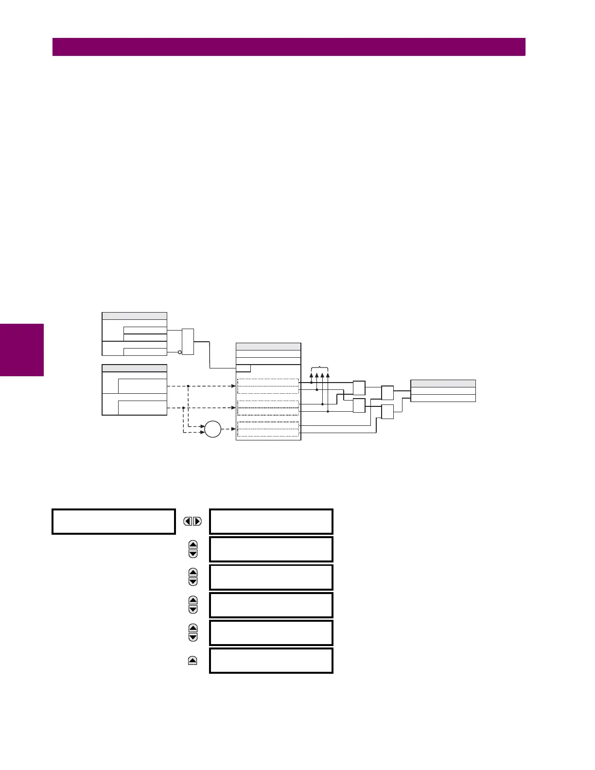
Figure 5–50: NEGATIVE-SEQUENCE OVERCURRENT ADVANCED FAULT DETECTOR LOGIC
h) POSITIVE-SEQUENCE OVERCURRENT FAULT DETECTION
PATH: SETTINGS ÖØ GROUPED ELEMENTS Ö PHASE COMPARISON ELEMENTS ÖØ ADVANCED FAULT DETECTORS
ÖØ POSITIVE-SEQUENCE CURRENT
POSITIVE-SEQUENCE
CURRENT
POS SEQ I_1 FD
FUNCTION: Disabled
Range: Disabled, Enabled
MESSAGE
POS SEQ I_1 FDL
PICKUP: 0.10 pu
Range: 0.20 to 5.00 pu in steps of 0.01
MESSAGE
POS SEQ I_1 FDH
PICKUP: 0.50 pu
Range: 0.50 to 15.00 pu in steps of 0.01
MESSAGE
POS SEQ I_1 BLK:
Off
Range: FlexLogic™ operand
MESSAGE
POS SEQ I_1 FD
TARGET: Self-reset
Range: Self-Reset, Latched, Disabled
MESSAGE
POS SEQ I_1 FD
EVENTS: Disabled
Range: Disabled, Enabled
Hardwired to the
87PC function
To square pulse
and transmit logic
SETTINGS
Enabled = 1
Disabled = 0
NEG SEQ I_2 FD FUNCTION
Off=0
NEG SEQ I_2 BLOCK
AND
FAST MEASUREMENTS
Negative-sequence
current I_2
F1 PHASE CT BANK
L1 PHASE CT BANK
Negative-sequence
current I_2
Σ
SETTINGS
NEG SEQ I_2 FDH PICKUP
RUN
NEG SEQ I_2 FDL PICKUP
> (FDL PICKUP) / 4
> (FDH PICKUP) / 4
> (FDL PICKUP) / 4
> (FDH PICKUP) / 4
> FDL PICKUP
> FDH PICKUP
OR
OR
AND
AND
FLEXLOGIC OPERANDS
87PC I_2 FDL OP
87PC I_2 FDH OP
831030A1.CDR

 Loading...


