5-122 L60 Line Phase Comparison System GE Multilin
5.5 GROUPED ELEMENTS 5 SETTINGS
5
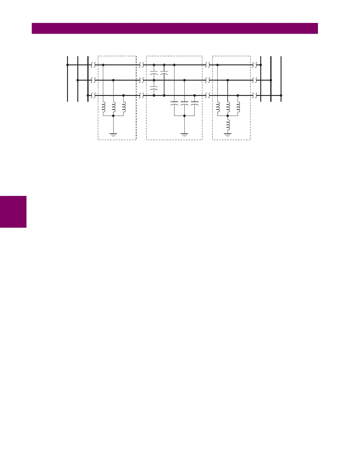
Figure 5–52: CHARGING CURRENT COMPENSATION CONFIGURATIONS
• CHARGE COMPENST BLOCK: This setting selects an input to block charging current compensation. This input is
typically the VT fuse fail element of the source, where the three-phase VT is configured with this setting to block com-
pensation. Blocking charging current compensation at one end of the line does not block charging current compensa-
tion on the other end. However, even with compensation operating at one end ½ (or 1/3) of the charging current is still
removed from the net phase comparison current. Alternatively, the customer may choose to switch to another setting
group with more conservative phase comparison settings during a VT fuse fail condition.
• POSITIVE and ZERO SEQUENCE CAPACITIVE REACTANCE: The values of positive and zero sequence capacitive
reactance of the protected line are required for charging current compensation calculations. The line capacitive reac-
tance values should be entered in primary kilo-ohms for the total line length. Details of the charging current compen-
sation algorithm can be found in Chapter 8: Theory of operation.
If shunt reactors are also installed on the line, the resulting value entered in the
POS SEQ CAPACITIVE REACTANCE and
ZERO SEQ CAPACITIVE REACTANCE settings should be calculated as follows:
1. No shunt reactors on the line or reactor current is subtracted from the line current, forcing the L60 to measure the
uncompensated by shunt reactors load/fault current plus the full charging current.
(EQ 5.7)
2. Three-reactor arrangement: three identical line reactors (X
react
) solidly connected phase to ground.
(EQ 5.8)
3. Four-reactor arrangement: three identical line reactors (X
react
) wye-connected with the fourth reactor (X
react_n
)
connected between reactor-bank neutral and the ground.
(EQ 5.9)
X
1line_capac
= the total line positive-sequence capacitive reactance
X
0line_capac
= the total line zero-sequence capacitive reactance
X
react
= the total reactor inductive reactance per phase. If identical reactors are installed at both ends of the line,
the inductive reactance is divided by 2 (or 3 for a three-terminal line) before inserting in the above equa-
tions. If the reactors installed at both ends of the line are different, the following equations apply:
1. For a two-terminal line:
2. For a three-terminal line:
X
react_n
= the total neutral reactor inductive reactance. If identical reactors are installed at both ends of the line,
the inductive reactance is divided by 2 (or 3 for a three-terminal line) before inserting in the above
equations. If the reactors installed at both ends of the line are different, the following equations apply:
Possible 3-Reactor
arrangement
Line Capacitive Reactance
Xreact Xreact
Xreact_n
X1line_capac
X0line_capac
Possible 4-Reactor
arrangement
A B C A B C
831731A3.CDR
X
C1
X
1line_capac
= , X
C0
X
0line_capac
=
X
C1
X
1line_capac
X
react
⋅
X
react
X
1line_capac
–
------------------------------------------------= , X
C0
X
0line_capac
X
react
⋅
X
react
X
0line_capac
–
------------------------------------------------=
X
C1
X
1line_capac
X
react
⋅
X
react
X
1line_capac
–
------------------------------------------------= , X
C0
X
0line_capac
X
react
3+ X
react_n
()⋅
X
react
3+ X
react_n
X
0line_capac
–
---------------------------------------------------------------------------------=
X
react
1
1
X
react_terminal1
-----------------------------------
1
X
react_terminal2
-----------------------------------+
⎝⎠
⎛⎞
⁄=
X
react
1
1
X
react_terminal1
-----------------------------------
1
X
react_terminal2
-----------------------------------
1
X
react_terminal3
-----------------------------------++
⎝⎠
⎛⎞
⁄=

 Loading...


