ADDENDUM
This addendum contains information that relates to the L60 Line Phase Comparison System, version 5.6x. This adden-
dum lists a number of information items that appear in the instruction manual GEK-113487A (revision T2) but are not
included in the current L60 operations.
The following functions and items are not yet available with the current version of the L60 relay:
• Signal sources SRC 5 and SRC 6.
• Advanced fault detectors: With the current version of the L60 relay, the advanced fault detectors are available on
50 Hz system applications only.
Version 4.0x and higher releases of the L60 relay includes new hardware (CPU and CT/VT modules).
• The new CPU modules are specified with the following order codes: 9E, 9G, 9H, 9J, 9K, 9L, 9M, 9N, 9P, 9R, and 9S.
• The new CT/VT modules are specified with the following order codes: 8F, 8H, 8L, 8N 8P.
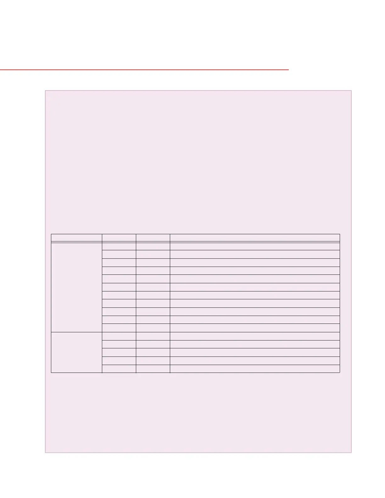
The following table maps the relationship between the old CPU and CT/VT modules to the newer versions:
The new CT/VT modules can only be used with the new CPUs (9E, 9G, 9H, 9J, 9K, 9L, 9M, 9N, 9P, 9R, and 9S), and
the old CT/VT modules can only be used with the old CPU modules (9A, 9C, 9D). To prevent any hardware mis-
matches, the new CPU and CT/VT modules have blue labels and a warning sticker stating “Attn.: Ensure CPU and
DSP module label colors are the same!”. In the event that there is a mismatch between the CPU and CT/VT module,
the relay will not function and a
DSP ERROR or HARDWARE MISMATCH error will be displayed.
All other input/output modules are compatible with the new hardware.
With respect to the firmware, firmware versions 4.0x and higher are only compatible with the new CPU and CT/VT mod-
ules. Previous versions of the firmware (3.4x and earlier) are only compatible with the older CPU and CT/VT modules.
MODULE OLD NEW DESCRIPTION
CPU 9A 9E RS485 and RS485 (Modbus RTU, DNP)
9C 9G RS485 and 10Base-F (Ethernet, Modbus TCP/IP, DNP)
9D 9H RS485 and redundant 10Base-F (Ethernet, Modbus TCP/IP, DNP)
--- 9J RS485 and multi-mode ST 100Base-FX
--- 9K RS485 and multi-mode ST redundant 100Base-FX
--- 9L RS485 and single mode SC 100Base-FX
--- 9M RS485 and single mode SC redundant 100Base-FX
--- 9N RS485 and 10/100Base-T
--- 9P RS485 and single mode ST 100Base-FX
--- 9R RS485 and single mode ST redundant 100Base-FX
--- 9S RS485 and six-port managed Ethernet switch
CT/VT 8A 8F Standard 4CT/4VT
8C 8H Standard 8CT
-- 8L Standard 4CT/4VT with enhanced diagnostics
-- 8N Standard 8CT with enhanced diagnostics
-- 8P Special 4CT module with communications channel for L60
Addendum
 Loading...


