GE Multilin L60 Line Phase Comparison System 5-197
5 SETTINGS 5.5 GROUPED ELEMENTS
5
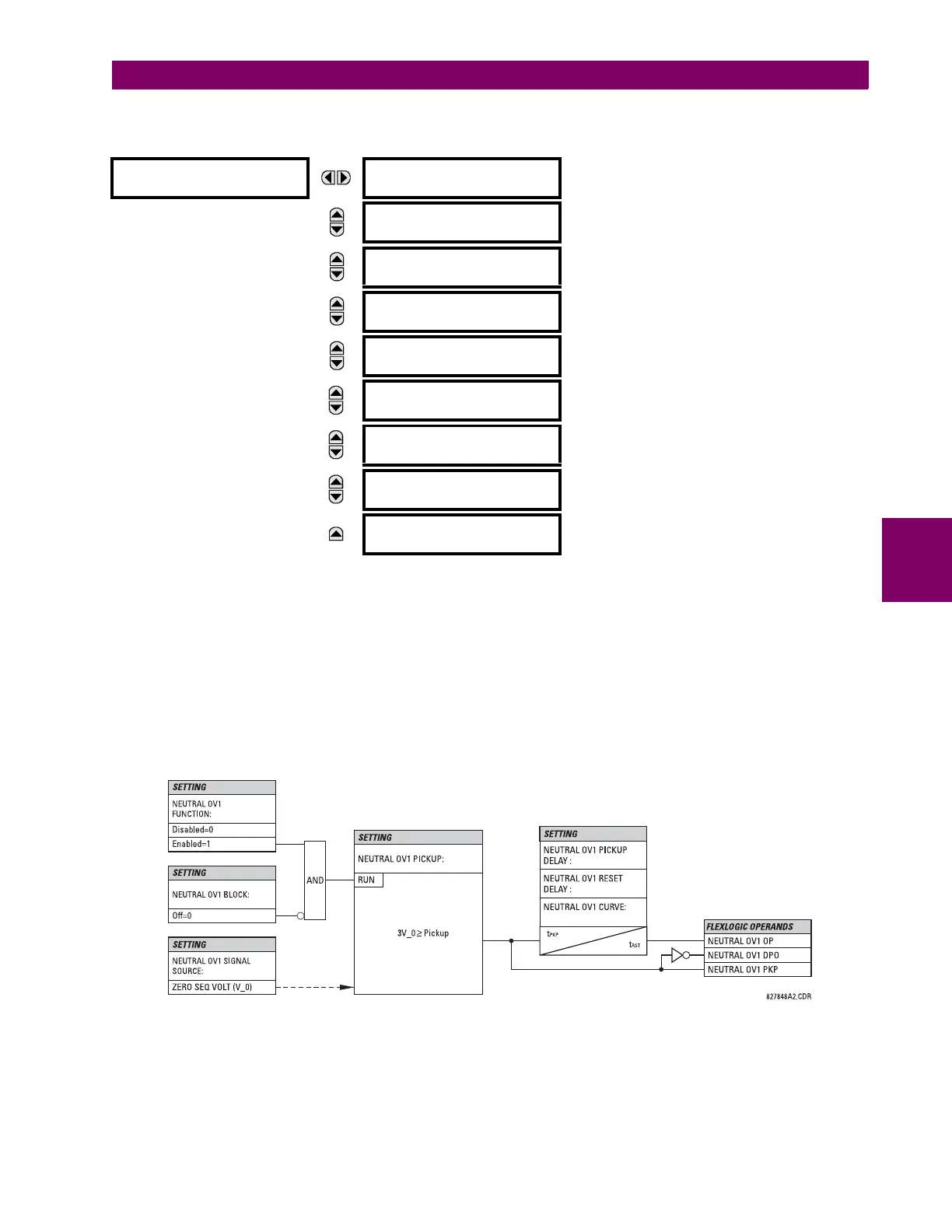
d) NEUTRAL OVERVOLTAGE (ANSI 59N)
PATH: SETTINGS ÖØ GROUPED ELEMENTS Ö SETTING GROUP 1(6) ÖØ VOLTAGE ELEMENTS ÖØ NEUTRAL OV1(3)
There are three neutral overvoltage elements available. The neutral overvoltage element can be used to detect asymmetri-
cal system voltage condition due to a ground fault or to the loss of one or two phases of the source. The element responds
to the system neutral voltage (3V_0), calculated from the phase voltages. The nominal secondary voltage of the phase volt-
age channels entered under
SETTINGS ÖØ SYSTEM SETUP Ö AC INPUTS ÖØ VOLTAGE BANK Ö PHASE VT SECONDARY is the
p.u. base used when setting the pickup level.
The neutral overvoltage element can provide a time-delayed operating characteristic versus the applied voltage (initialized
from FlexCurves A, B, or C) or be used as a definite time element. The NEUTRAL OV1 PICKUP DELAY setting applies only if
the NEUTRAL OV1 CURVE setting is “Definite time”. The source assigned to this element must be configured for a phase VT.
VT errors and normal voltage unbalance must be considered when setting this element. This function requires the VTs to
be wye-connected.
Figure 5–108: NEUTRAL OVERVOLTAGE1 SCHEME LOGIC
NEUTRAL OV1
NEUTRAL OV1
FUNCTION: Disabled
Range: Disabled, Enabled
MESSAGE
NEUTRAL OV1 SIGNAL
SOURCE: SRC 1
Range: SRC 1, SRC 2, SRC 3, SRC 4
MESSAGE
NEUTRAL OV1 PICKUP:
0.300 pu
Range: 0.000 to 3.000 pu in steps of 0.001
MESSAGE
NEUTRAL OV1 CURVE:
Definite time
Range: Definite time, FlexCurve A, FlexCurve B,
FlexCurve C
MESSAGE
NEUTRAL OV1 PICKUP:
DELAY: 1.00 s
Range: 0.00 to 600.00 s in steps of 0.01
MESSAGE
NEUTRAL OV1 RESET:
DELAY: 1.00 s
Range: 0.00 to 600.00 s in steps of 0.01
MESSAGE
NEUTRAL OV1 BLOCK:
Off
Range: FlexLogic™ operand
MESSAGE
NEUTRAL OV1 TARGET:
Self-reset
Range: Self-reset, Latched, Disabled
MESSAGE
NEUTRAL OV1 EVENTS:
Disabled
Range: Disabled, Enabled

 Loading...


