5-200 L60 Line Phase Comparison System GE Multilin
5.5 GROUPED ELEMENTS 5 SETTINGS
5
g) AUXILIARY OVERVOLTAGE (ANSI 59X)
PATH: SETTINGS ÖØ GROUPED ELEMENTS Ö SETTING GROUP 1(6) ÖØ VOLTAGE ELEMENTS ÖØ AUXILIARY OV1(2)
The L60 contains one auxiliary overvoltage element for each VT bank. This element is intended for monitoring overvoltage
conditions of the auxiliary voltage. The nominal secondary voltage of the auxiliary voltage channel entered under
SYSTEM
SETUP Ö AC INPUTS ØÖ VOLTAGE BANK X5 ØÖ AUXILIARY VT X5 SECONDARY is the per-unit (pu) base used when setting the
pickup level.
A typical application for this element is monitoring the zero-sequence voltage (3V_0) supplied from an open-corner-delta
VT connection.
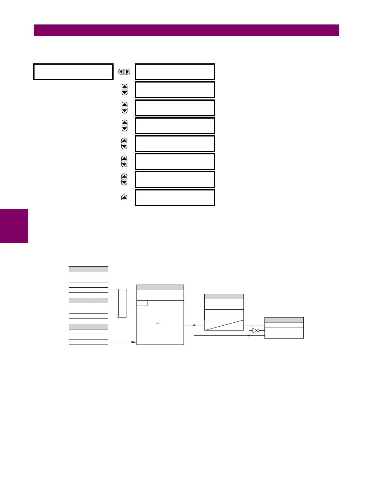
Figure 5–111: AUXILIARY OVERVOLTAGE SCHEME LOGIC
AUXILIARY OV1
AUX OV1
FUNCTION: Disabled
Range: Disabled, Enabled
MESSAGE
AUX OV1 SIGNAL
SOURCE: SRC 1
Range: SRC 1, SRC 2
MESSAGE
AUX OV1 PICKUP:
0.300 pu
Range: 0.000 to 3.000 pu in steps of 0.001
MESSAGE
AUX OV1 PICKUP
DELAY: 1.00 s
Range: 0.00 to 600.00 s in steps of 0.01
MESSAGE
AUX OV1 RESET
DELAY: 1.00 s
Range: 0.00 to 600.00 s in steps of 0.01
MESSAGE
AUX OV1 BLOCK:
Off
Range: FlexLogic™ operand
MESSAGE
AUX OV1 TARGET:
Self-reset
Range: Self-reset, Latched, Disabled
MESSAGE
AUX OV1 EVENTS:
Disabled
Range: Disabled, Enabled
827836A2.CDR
FLEXLOGIC OPERANDS
AUX OV1
FUNCTION:
AUX OV1 BLOCK:
AUX OV1 SIGNAL
SOURCE:
AUX OV1 PICKUP:
AUX OV1 DPO
AUX OV1 OP
AUX OV1 PKP
RUN
AND
SETTING
SETTING
AUX OV1 RESET
DELAY :
AUX OV1 PICKUP
DELAY :
SETTING
Enabled=1
Disabled=0
t
PKP
tRST
SETTING
SETTING
Off=0
AUXILIARY VOLT (Vx)
Vx Pickup
<

 Loading...


