8-4 L60 Line Phase Comparison System GE Multilin
8.1 OVERVIEW 8 THEORY OF OPERATION
8
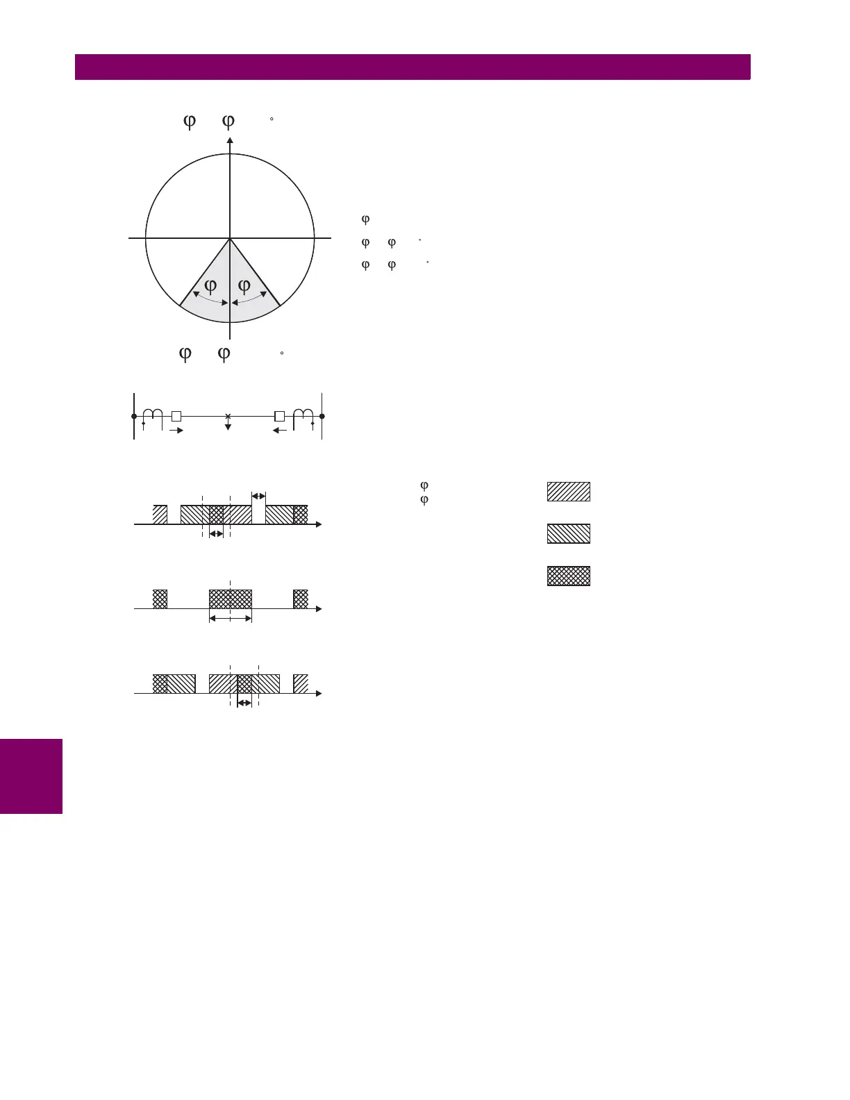
Figure 8–3: STABILITY ANGLE
Figures 8–4A, 8–4B, 8–4C, and 8–4D are for three-terminal lines and they correspond directly to Figures 8–2A, 8–2B, 8–
2C, and 8–2D. It will be noted from Figure 8–3 that for a three-terminal line, the relay at A must receive information from
both the remote terminals. The same applies to the relays at terminals B and C. As in the case of the two-terminal lines, the
integrator illustrated in Figure 8–4 will actually be set for 3 to 4 ms.
While all the sketches in Figures 8–2 and 8–4 compare the positive half cycle of current with a receiver output, the negative
half cycle might just as well have been selected. However, if this were done, in Figure 8–2A for example, it would have
been necessary to compare the presence of negative current with a received SPACE signal rather than a MARK signal.
It should be recognized that the above discussion, as well as Figures 8–1 and 8–2, are rudimentary. The complete phase
comparison scheme is considerably more sophisticated and will be discussed in more detail subsequently. However, at this
point it would be well to note that phase comparison on a continuous basis is not permitted mainly because it would tend to
reduce the security of the scheme. For this reason, fault detectors are provided. They initiate phase comparison only when
a fault occurs on, or in the general vicinity of, the protected line. A simplified sketch of the logic of a phase comparison
blocking scheme including fault detectors is illustrated in Figure 8–5. This is a somewhat more fully developed version of
Figure 8–2D, and the same logic is present at both ends of a two-terminal line.
831724A2.CDR
TRIPPING
BLOCKING
ss
s-STABILITY ANGLE SETTING
( X)- ( Y)=0 FOR INTERNALFAULTSAND CURRENTSARE IDEALLY IN PHASE
( X)- ( Y)=180 FOR EXTERNALFAULT AND CURRENT ARE IDEALLY IN OPPOSITE DIRECTIONS
II
II
SQUARE SIGNALY
LEADINGSQUARE SIGNALX
SIGNALX
SIGNALY
TIME OF COINCIDENCE
OF SIGNALS X AND Y
tCOINCIDENCE > s TRIPPING
tCOINCIDENCE <sBLOCKING
SQUARE SIGNAL Y COINCIDES
SQUARE SIGNALX
SQUARE SIGNALY LAGGING
SQUARE SIGNALX
(I )- (I )=180XY
t COINCIDENCE
t GAP
t COINCIDENCE
t COINCIDENCE
(I )- (I )=0XY
t
t
t
IX
BUS X BUS Y
FAULT IY

 Loading...


