30
Fn_14: Stopping method = 0 : decelerate stop
1 : free run stop
Fn_15: DC braking time = 0 up to 25.5 sec
Fn_16: DC braking starting frequency = 1 up to 10Hz
Fn_17: DC braking level = 0 up to 20%
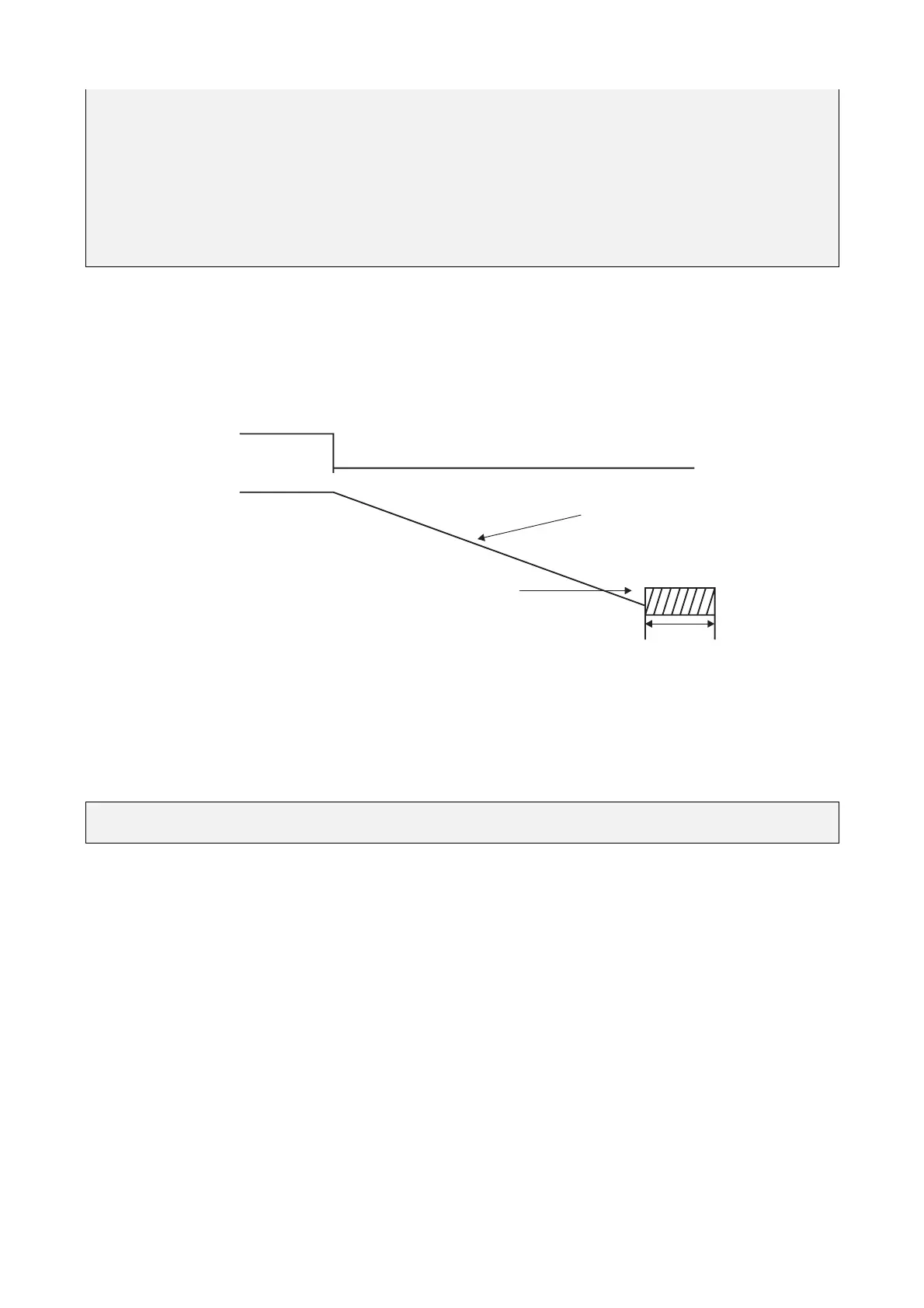
If Fn_14 = 0
When the inverter receive the stop instruction, it decelerate to the frequency setup by Fn_16 and
then output voltage level setup in the Fn_17; after the time duration setup in Fn_15, the inverter
turn into complete stop.
DC braking frequency
Output frequency
Deceleration time
DC braking time
Run command
If Fn_14 = 1
The inverter stop output immediately after receiving stop instruction. The motor get into free running
state to completely stop.
Fn_18: Motor rated current = 50 up to 100 % or 0 up to 200%
(*)
(*) Only for drives with CPU version from 1.9 (check fnction F_29)
1. Function of the electronic thermal protecting motor
(1) Motor rated current = Inverter rated current x Fn_18
Fn_18 = Motor rated current / inverter rated current
(2) When the load is within 100% of the motor rated current, the operation continues. When the
load reaches 150% of the motor rated current the operation may continues for only 1 minute.
(refer to curve (1) in figures 3)
(3) After protecting the motor with the electronic thermal switch activated, the inverter is cut off
immediately. The OLI light will flash. To resume operation, push the RESET button or activate
an external reset connection wired to terminal 2.
(4) When the motor is operating at low speeds, the heat dissipation efficiency is lower. The
electronic thermal activation level is also reduced. (to change from curve (1) to curve (2) in
Figure 3. Choose the appropriate Fn_05 setting according to the applied motor to reach the
desired performance.