31
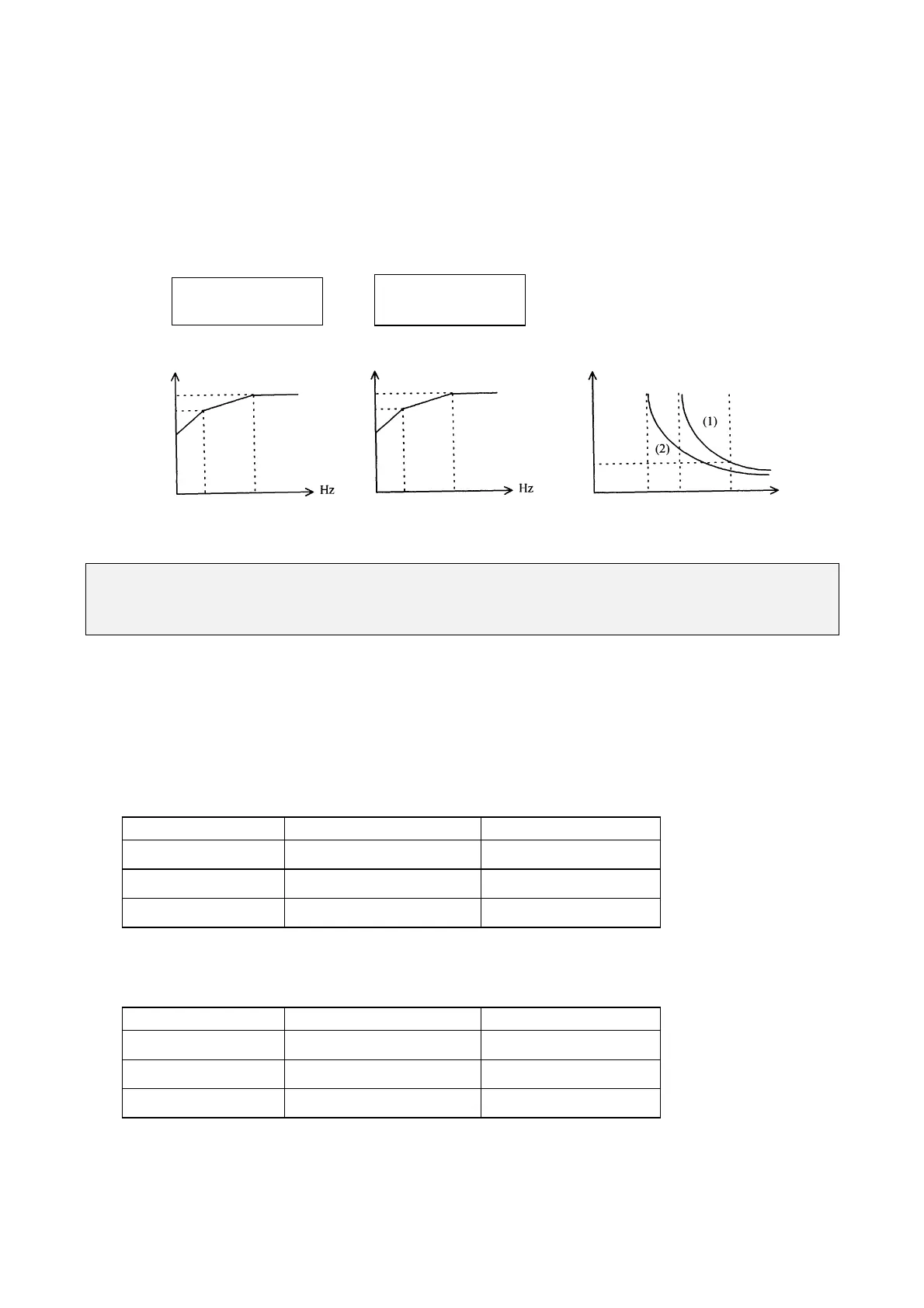
2. Function of the electronic thermal protecting inverter
(1) When the load is within 103% of the inverters rated current, the operation continues.
When the load reaches 150% of rated current of the inverter, the operation will continue
for 1 minute. ( Refer to curve (1) of figure 3)
(2) After the activation of the electronic thermal switch, the inverter is shut off immediately.
The OL2 light will flash. To resume the operation, push RESET button or activate an external
reset contact on terminal 2.
Fn_19: Multifunction input terminal 1 function = 1 up to 5 or 6
(*)
Fn_20: Multifunction input terminal 2 function = 1 up to 5 or 6
(*)
(*) Only for drives with CPU version from 1.9 (check fnction F_29)
1. Fn_19, Fn_20 =1 : JOG (refer to F_09)
2. Fn_19, Fn_20 = 2 or 6 multispeed control
Multi-speed control (only for drives with CPU version from 1.9)
F_19 = 2 and F_20 = 6
TM2 SP1 Terminal TM2 RESET Terminal Output frequency
ON OFF (F_08)
OFF ON (F_26)
ON ON (F_27)
F_19 = 6 and F_20 = 2
TM2 SP1 Terminal TM2 RESET Terminal Output frequency
ON OFF (F_26)
OFF ON (F_08)
ON ON SP3 (F_27)
Fn_05 = 1,2,3
50 Hz standard motor
%
Fn_05 = 4,5,6
60 Hz standard motor
100
90
60
Derating
100
90
60
Decay
Derating %
20 50 (Fig. 1)
20 60 (Fig. 2)
(Fig. 3) 100 150 Percentage of
Current
1.0
 Loading...


